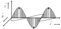
 (1) \[\overrightarrow{E}\] and \[\overrightarrow{B}\] always oscillates in phase.
(2) \[\overrightarrow{E}\] and \[\overrightarrow{B}\] are such that \[\overrightarrow{E}\times \overrightarrow{B}\] is always in the direction of propagation of wave.
(1) \[\overrightarrow{E}\] and \[\overrightarrow{B}\] always oscillates in phase.
(2) \[\overrightarrow{E}\] and \[\overrightarrow{B}\] are such that \[\overrightarrow{E}\times \overrightarrow{B}\] is always in the direction of propagation of wave.
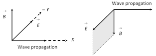 (3) The EM wave propagating in the positive x-direction may be represented by
\[E={{E}_{y}}={{E}_{0}}\sin (kx-\omega t)\]
\[B={{B}_{z}}={{B}_{0}}\sin (kx-\omega t)\]
where E (or \[{{E}_{y}}\]), B (or \[{{B}_{z}}\]) are the instantaneous values of the fields, \[{{E}_{0}}\], \[{{B}_{0}}\] are amplitude of the fields and K = angular wave number\[=\frac{2\pi }{\lambda }\].
(3) The EM wave propagating in the positive x-direction may be represented by
\[E={{E}_{y}}={{E}_{0}}\sin (kx-\omega t)\]
\[B={{B}_{z}}={{B}_{0}}\sin (kx-\omega t)\]
where E (or \[{{E}_{y}}\]), B (or \[{{B}_{z}}\]) are the instantaneous values of the fields, \[{{E}_{0}}\], \[{{B}_{0}}\] are amplitude of the fields and K = angular wave number\[=\frac{2\pi }{\lambda }\]. 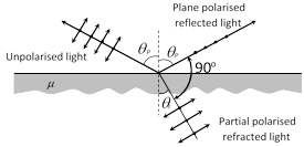 From fig. it is clear that \[{{\theta }_{p}}+{{\theta }_{r}}={{90}^{o}}\]
Also \[\mu =\tan {{\theta }_{p}}\] Brewster's law
(i) For \[i<{{\theta }_{p}}\] or \[i>{{\theta }_{p}}\]
Both reflected and refracted rays becomes partially polarized
(ii) For glass \[{{\theta }_{P}}\approx {{57}^{o}},\] for water \[{{\theta }_{P}}\approx {{53}^{o}}\]
(2) By Dichroism : Some crystals such as tourmaline and sheets of iodosulphate of quinine have the property of strongly absorbing the light with vibrations perpendicular to a specific direction (called transmission axis) transmitting the light with vibrations parallel to it. This selective absorption of light is called dichroism.
(3) By double refraction : In certain crystals, like calcite, quartz and tourmaline etc, incident unpolarized light splits up into two light beams of equal intensities with perpendicular polarization.
From fig. it is clear that \[{{\theta }_{p}}+{{\theta }_{r}}={{90}^{o}}\]
Also \[\mu =\tan {{\theta }_{p}}\] Brewster's law
(i) For \[i<{{\theta }_{p}}\] or \[i>{{\theta }_{p}}\]
Both reflected and refracted rays becomes partially polarized
(ii) For glass \[{{\theta }_{P}}\approx {{57}^{o}},\] for water \[{{\theta }_{P}}\approx {{53}^{o}}\]
(2) By Dichroism : Some crystals such as tourmaline and sheets of iodosulphate of quinine have the property of strongly absorbing the light with vibrations perpendicular to a specific direction (called transmission axis) transmitting the light with vibrations parallel to it. This selective absorption of light is called dichroism.
(3) By double refraction : In certain crystals, like calcite, quartz and tourmaline etc, incident unpolarized light splits up into two light beams of equal intensities with perpendicular polarization.
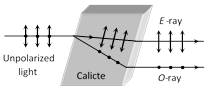 (i) One of the ray is ordinary ray (O-ray) it obey's the Snell's law. Another ray's extra ordinary ray (E-ray) it doesn't obey's the Snell's law.
(ii) Along a particular direction (fixed in the crystal, the two velocities (velocity of O-ray \[{{v}_{o}}\] and velocity of E-ray \[{{v}_{e}}\]) are equal; this direction is known as the optic axis of the crystal (crystal's known as uniaxial crystal). Optic axis is a direction and not any line in crystal.
(iii) In the direction, perpendicular to the optic axis for negative crystal (calcite) \[{{v}_{e}}>{{v}_{o}}\] and \[{{\mu }_{e}}<{{\mu }_{o}}\].
For positive crystal \[{{v}_{e}}~<{{v}_{o}}\], \[{{\mu }_{e}}~>{{\mu }_{o}}\].
(4) Nicol prism : Nicol prism is made up of calcite crystal and in it E-ray is isolated from O-ray through total internal reflection of O-ray at canada balsam layer and then absorbing it at the blackened surface as shown in fig.
(i) One of the ray is ordinary ray (O-ray) it obey's the Snell's law. Another ray's extra ordinary ray (E-ray) it doesn't obey's the Snell's law.
(ii) Along a particular direction (fixed in the crystal, the two velocities (velocity of O-ray \[{{v}_{o}}\] and velocity of E-ray \[{{v}_{e}}\]) are equal; this direction is known as the optic axis of the crystal (crystal's known as uniaxial crystal). Optic axis is a direction and not any line in crystal.
(iii) In the direction, perpendicular to the optic axis for negative crystal (calcite) \[{{v}_{e}}>{{v}_{o}}\] and \[{{\mu }_{e}}<{{\mu }_{o}}\].
For positive crystal \[{{v}_{e}}~<{{v}_{o}}\], \[{{\mu }_{e}}~>{{\mu }_{o}}\].
(4) Nicol prism : Nicol prism is made up of calcite crystal and in it E-ray is isolated from O-ray through total internal reflection of O-ray at canada balsam layer and then absorbing it at the blackened surface as shown in fig.
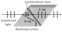 The refractive index for the O-ray is more that for the E-ray. The refractive index of Canada balsam lies between the refractive indices of calcite for the O-ray and E-ray
(5) By Scattering : It is found that scattered light in directions perpendicular to the direction of incident light is completely plane polarised while transmitted light is unpolarised. Light in all other directions is partially polarised.
(6) Optical activity and specific rotation : When plane polarised light passes through certain substances, the plane of polarisation of the light is rotated about the direction of propagation of light through a certain angle. This phenomenon is called optical activity or optical rotation and the substances optically active.
The refractive index for the O-ray is more that for the E-ray. The refractive index of Canada balsam lies between the refractive indices of calcite for the O-ray and E-ray
(5) By Scattering : It is found that scattered light in directions perpendicular to the direction of incident light is completely plane polarised while transmitted light is unpolarised. Light in all other directions is partially polarised.
(6) Optical activity and specific rotation : When plane polarised light passes through certain substances, the plane of polarisation of the light is rotated about the direction of propagation of light through a certain angle. This phenomenon is called optical activity or optical rotation and the substances optically active.
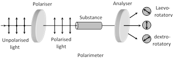 If the optically active substance rotates the plane of polarisation clockwise (looking against the direction of light), it is said to be dextro-rotatory or right-handed. However, if the substance rotates the plane of polarisation anti-clockwise, it is called laevo-rotatory or left-handed.
The optical activity of a more...
If the optically active substance rotates the plane of polarisation clockwise (looking against the direction of light), it is said to be dextro-rotatory or right-handed. However, if the substance rotates the plane of polarisation anti-clockwise, it is called laevo-rotatory or left-handed.
The optical activity of a more... 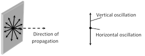 (2) Polarised light : The phenomenon of limiting the vibrating of electric field vector in one direction in a plane perpendicular to the direction of propagation of light wave is called polarization of light.
(i) The plane in which oscillation occurs in the polarised light is called plane of oscillation.
(ii) The plane perpendicular to the plane of oscillation is called plane of polarisation.
(iii) Light can be polarised by transmitting through certain crystals such as tourmaline or polaroids.
(3) Polaroids : It is a device used to produce the plane polarised light. It is based on the principle of selective absorption and is more effective than the tourmaline crystal.
Or
It is a thin film of ultramicroscopic crystals of quinine idosulphate with their optic axis parallel to each other.
(2) Polarised light : The phenomenon of limiting the vibrating of electric field vector in one direction in a plane perpendicular to the direction of propagation of light wave is called polarization of light.
(i) The plane in which oscillation occurs in the polarised light is called plane of oscillation.
(ii) The plane perpendicular to the plane of oscillation is called plane of polarisation.
(iii) Light can be polarised by transmitting through certain crystals such as tourmaline or polaroids.
(3) Polaroids : It is a device used to produce the plane polarised light. It is based on the principle of selective absorption and is more effective than the tourmaline crystal.
Or
It is a thin film of ultramicroscopic crystals of quinine idosulphate with their optic axis parallel to each other.
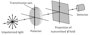 (i) Polaroids allow the light oscillations parallel to the transmission axis pass through them.
(ii) The crystal or polaroid on which unpolarised light is incident is called polariser. Crystal or polaroid on which polarised light is incident is called analyser.
(i) Polaroids allow the light oscillations parallel to the transmission axis pass through them.
(ii) The crystal or polaroid on which unpolarised light is incident is called polariser. Crystal or polaroid on which polarised light is incident is called analyser.
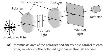
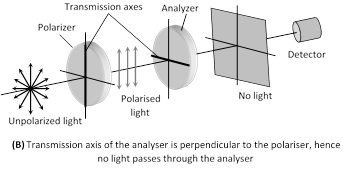 (4) Malus law : This law states that the intensity of the polarised light transmitted through the analyser varies as the square of the cosine of the angle between the plane of transmission of the analyser and the plane of the polariser.
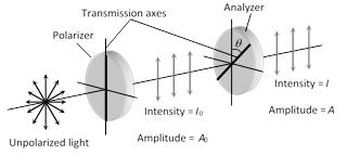 (i) \[I={{I}_{0}}{{\cos }^{2}}\theta \] and\[{{A}^{2}}=A_{0}^{2}{{\cos }^{2}}\theta \]\[\Rightarrow \]\[A={{A}_{0}}\cos \theta \]
If \[\theta ={{0}^{o}}\], \[I={{I}_{0}}\], \[A={{A}_{0}}\], If \[\theta ={{90}^{o}}\], \[I=0\], \[A=0\]
(ii) If \[{{I}_{i}}=\] Intensity of unpolarised light.
So \[{{I}_{0}}=\frac{{{I}_{i}}}{2}\] i.e. if an unpolarised light is converted into plane polarised light (say by passing it through a Polaroid or a Nicol-prism), its intensity becomes half. and \[I=\frac{{{I}_{i}}}{2}{{\cos }^{2}}\theta \]
(i) \[I={{I}_{0}}{{\cos }^{2}}\theta \] and\[{{A}^{2}}=A_{0}^{2}{{\cos }^{2}}\theta \]\[\Rightarrow \]\[A={{A}_{0}}\cos \theta \]
If \[\theta ={{0}^{o}}\], \[I={{I}_{0}}\], \[A={{A}_{0}}\], If \[\theta ={{90}^{o}}\], \[I=0\], \[A=0\]
(ii) If \[{{I}_{i}}=\] Intensity of unpolarised light.
So \[{{I}_{0}}=\frac{{{I}_{i}}}{2}\] i.e. if an unpolarised light is converted into plane polarised light (say by passing it through a Polaroid or a Nicol-prism), its intensity becomes half. and \[I=\frac{{{I}_{i}}}{2}{{\cos }^{2}}\theta \]  The resultant amplitude due to this zone plate in
\[R={{R}_{1}}+{{R}_{3}}+{{R}_{5}}+..........>>\frac{{{R}_{1}}}{2}\]
Thus, intensity of light tremendously increases.
(3) Negative zone plate : when even zones are kept transparent to light and odd zones are made opaque, then it is called negative zone plate.
The resultant amplitude due to this zone plate in
\[R={{R}_{1}}+{{R}_{3}}+{{R}_{5}}+..........>>\frac{{{R}_{1}}}{2}\]
Thus, intensity of light tremendously increases.
(3) Negative zone plate : when even zones are kept transparent to light and odd zones are made opaque, then it is called negative zone plate.
 The resultant amplitude due to this zone plate is
\[R={{R}_{2}}+{{R}_{4}}+{{R}_{6}}+..........>>\frac{{{R}_{1}}}{2}\]
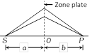
(4) Zone plate behaves like a convex lens. For a plane wave front the image of source is formed at distance d i.e. d is equal to the principle focal length or first focal length \[{{f}_{1}}=d=\frac{{{r}^{2}}}{\lambda }\]
(5) Multiple focii of zone plate are given by \[{{f}_{p}}=\frac{{{r}^{2}}}{(2p-1)\lambda }\] where p = 1, 2, 3,......... represents the order of foci
(6) If the radius of nth circle on zone plate is \[{{r}_{n}}\] then in terms of \[{{r}_{n}}\].
Principal focal length \[{{f}_{1}}=\frac{r_{n}^{2}}{n\lambda }\]
Other focal length \[{{f}_{p}}=\frac{r_{n}^{2}}{(2p-1)n\lambda }\]
(7) If a is the distance of the source from the zone plate then the distance b of the point where maximum intensity is observes is given by \[\frac{1}{a}+\frac{1}{b}=\frac{n\lambda }{r_{n}^{2}}\]
The resultant amplitude due to this zone plate is
\[R={{R}_{2}}+{{R}_{4}}+{{R}_{6}}+..........>>\frac{{{R}_{1}}}{2}\]
(4) Zone plate behaves like a convex lens. For a plane wave front the image of source is formed at distance d i.e. d is equal to the principle focal length or first focal length \[{{f}_{1}}=d=\frac{{{r}^{2}}}{\lambda }\]
(5) Multiple focii of zone plate are given by \[{{f}_{p}}=\frac{{{r}^{2}}}{(2p-1)\lambda }\] where p = 1, 2, 3,......... represents the order of foci
(6) If the radius of nth circle on zone plate is \[{{r}_{n}}\] then in terms of \[{{r}_{n}}\].
Principal focal length \[{{f}_{1}}=\frac{r_{n}^{2}}{n\lambda }\]
Other focal length \[{{f}_{p}}=\frac{r_{n}^{2}}{(2p-1)n\lambda }\]
(7) If a is the distance of the source from the zone plate then the distance b of the point where maximum intensity is observes is given by \[\frac{1}{a}+\frac{1}{b}=\frac{n\lambda }{r_{n}^{2}}\]
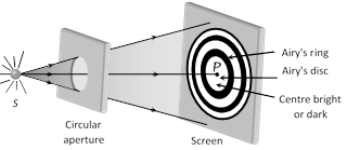 (1) If only one HPZ is allowed by the aperture then the resultant amplitude at P would be \[{{R}_{1}}\]which is twice the value of amplitude for the unobstructed wave front. The intensity would there fore be \[4{{l}_{0}},\] where \[{{l}_{0}}\]represents the intensity at point P, due to unobstructed wave front.
(2) If the first two HPZ's are permitted by aperture than the resultant intensity at the centre point P will be very small (as \[{{R}_{1}}-{{R}_{2}}\approx 0)\]. In this case the diffraction pattern consist of a bright circle of light with a dark spot.
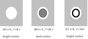
(3) In general if number of HPZ's (n) passing through aperture is odd, then the central point will be bright and if n is even, central point will be dark.
(1) If only one HPZ is allowed by the aperture then the resultant amplitude at P would be \[{{R}_{1}}\]which is twice the value of amplitude for the unobstructed wave front. The intensity would there fore be \[4{{l}_{0}},\] where \[{{l}_{0}}\]represents the intensity at point P, due to unobstructed wave front.
(2) If the first two HPZ's are permitted by aperture than the resultant intensity at the centre point P will be very small (as \[{{R}_{1}}-{{R}_{2}}\approx 0)\]. In this case the diffraction pattern consist of a bright circle of light with a dark spot.
(3) In general if number of HPZ's (n) passing through aperture is odd, then the central point will be bright and if n is even, central point will be dark.
 (4) The central bright disc is known as Airy's disc.
(5) In the non axial region bright and dark diffraction rings are obtained. The intensity of bright diffraction rings gradually goes on decreasing whereas that of dark diffraction goes on increasing.
(6) The first dark ring obtained around the central bright disc is known as Airy's ring.
(4) The central bright disc is known as Airy's disc.
(5) In the non axial region bright and dark diffraction rings are obtained. The intensity of bright diffraction rings gradually goes on decreasing whereas that of dark diffraction goes on increasing.
(6) The first dark ring obtained around the central bright disc is known as Airy's ring. 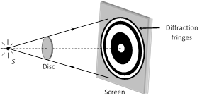 (1) At the centre of the circular shadow of disc, there occurs a bright spot. This spot is called Fresnel's spot or Poisson's spot.
(2) The intensity of bright spot decreases, when the size of the disc is increased or when the screen is moved towards the disc.
(3) Circular alternate bright and dark fringes are formed around the bright spot with fringe width in decreasing order.
(4) Let r be the radius of the disc, d is the distance between screen and the disc and \[\lambda \] is the wavelength of light used.
If n HPZ are covered by disc then \[nd\lambda =\pi {{r}^{2}}\Rightarrow n=\frac{{{r}^{2}}}{d\lambda }\]
(5) If the disc obstruct only first HPZ, the resultant amplitude at the central point\[R=-{{R}_{2}}+{{R}_{3}}+.........\approx -\frac{{{R}_{2}}}{2}\]
So intensity is \[\frac{kR_{2}^{2}}{4}\]which is slightly less than the intensity \[\frac{k\,R_{1}^{2}}{4}\] due to whole wave front, when no obstacle is placed.
(6) The intensity at bright spot is given by \[I=k{{\left[ \frac{{{R}_{n+1}}}{2} \right]}^{2}}\]
where n = Number of obstructed HPZ's
(1) At the centre of the circular shadow of disc, there occurs a bright spot. This spot is called Fresnel's spot or Poisson's spot.
(2) The intensity of bright spot decreases, when the size of the disc is increased or when the screen is moved towards the disc.
(3) Circular alternate bright and dark fringes are formed around the bright spot with fringe width in decreasing order.
(4) Let r be the radius of the disc, d is the distance between screen and the disc and \[\lambda \] is the wavelength of light used.
If n HPZ are covered by disc then \[nd\lambda =\pi {{r}^{2}}\Rightarrow n=\frac{{{r}^{2}}}{d\lambda }\]
(5) If the disc obstruct only first HPZ, the resultant amplitude at the central point\[R=-{{R}_{2}}+{{R}_{3}}+.........\approx -\frac{{{R}_{2}}}{2}\]
So intensity is \[\frac{kR_{2}^{2}}{4}\]which is slightly less than the intensity \[\frac{k\,R_{1}^{2}}{4}\] due to whole wave front, when no obstacle is placed.
(6) The intensity at bright spot is given by \[I=k{{\left[ \frac{{{R}_{n+1}}}{2} \right]}^{2}}\]
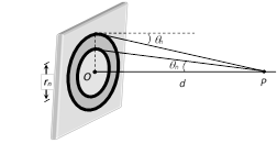
where n = Number of obstructed HPZ's 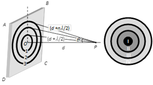 Suppose ABCD is a plane wave front. We desire to find it's effect at point P consider a sphere of radius \[\left( d+\frac{\lambda }{2} \right)\] with centre at P, then this sphere will cut the wave front in a circle (circle 1). This circular zone is called Fresnel's first (I) HPZ.
A sphere of radius \[b+2\left( \frac{\lambda }{2} \right)\] with centre at P will cut the wave front in circle 2, the annular region between circle 2 and circle 1 is called second (II) HPZ.
The peripheral area enclosed between the nth circle and \[{{(n-1)}^{\text{th}}}\]circle is defined as nth HPZ.
(1) Radius of HPZ : For nth HPZ, it is given by
\[{{r}_{n}}=\sqrt{nd\lambda }\,\,\,\Rightarrow {{r}_{n}}\propto \sqrt{\lambda }\]
Suppose ABCD is a plane wave front. We desire to find it's effect at point P consider a sphere of radius \[\left( d+\frac{\lambda }{2} \right)\] with centre at P, then this sphere will cut the wave front in a circle (circle 1). This circular zone is called Fresnel's first (I) HPZ.
A sphere of radius \[b+2\left( \frac{\lambda }{2} \right)\] with centre at P will cut the wave front in circle 2, the annular region between circle 2 and circle 1 is called second (II) HPZ.
The peripheral area enclosed between the nth circle and \[{{(n-1)}^{\text{th}}}\]circle is defined as nth HPZ.
(1) Radius of HPZ : For nth HPZ, it is given by
\[{{r}_{n}}=\sqrt{nd\lambda }\,\,\,\Rightarrow {{r}_{n}}\propto \sqrt{\lambda }\]
 (2) Area of HPZ : Area of nth HPZ is given by
\[{{A}_{n}}=\]Area of nth circle - Area of \[{{(n-1)}^{\text{th}}}\] circle
\[=\pi (r_{n}^{2}-r_{n-1}^{2})=\pi d\lambda \]
(3) Mean distance of the observation point P from nth HPZ : \[{{d}_{n}}=\frac{{{r}_{n}}+{{r}_{n-1}}}{2}=b+\frac{(2n-1)\lambda }{4}\]
(4) Phase difference between the HPZ : phase difference between the wavelets originating from two consecutive HPZ's and reaching the point P is \[\pi \](or path difference is \[\frac{\lambda }{2},\] time difference is \[\frac{T}{2}\]).
The phase difference between any two even or old number HPZ is \[2\pi \].
(5) Amplitude of HPZ : The amplitude of light at point P due to nth HPZ is \[{{R}_{n}}\propto \frac{{{A}_{n}}}{{{d}_{n}}}(1+\cos {{\theta }_{n}})\]; where \[{{A}_{n}}=\] Area of nth HPZ, \[{{d}_{n}}=\] Mean distance of nth HPZ
\[(1+\cos {{\theta }_{n}})\]= Obliquity factor.
On increasing the value of n, the value of \[{{R}_{n}}\] gradually goes on decreasing i.e. \[{{R}_{1}}>{{R}_{2}}>{{R}_{3}}>{{R}_{4}}>............>{{R}_{n-1}}>{{R}_{n}}\]
(6) Resultant Amplitude : The wavelets from two consecutive HPZ's meets in opposite phase at P.
Hence Resultant amplitude at P
\[R={{R}_{1}}-{{R}_{2}}+{{R}_{3}}-{{R}_{4}}+.........{{(-1)}^{\text{n-1}}}{{R}_{n}}\]
When \[n=\infty \], then \[{{R}_{n-1}}={{R}_{n}}=0,\]therefore \[R=\frac{{{R}_{1}}}{2}\]
i.e. For large number of HPZ, the amplitude of light at point P due to whole wave front is half the amplitude due to first HPZ.
The ratio of amplitudes due to consecutive HPZ's is constant and is less than 1
\[\frac{{{R}_{n}}}{{{R}_{n-1}}}........\frac{{{R}_{5}}}{{{R}_{4}}}=\frac{{{R}_{4}}}{{{R}_{3}}}=\frac{{{R}_{3}}}{{{R}_{2}}}=\frac{{{R}_{2}}}{{{R}_{1}}}=k\] (where \[k<1\])
(7) Resultant Intensity : Intensity \[\propto {{(\text{amplitude})}^{2}}\]
For \[n=\infty ,\]\[I\propto \frac{R_{1}^{2}}{4}\,\propto \,\frac{{{I}_{1}}}{4}\]
i.e. the resultant intensity due to whole wave front is \[\frac{1}{4}th\] the intensity due to first HPZ.
(2) Area of HPZ : Area of nth HPZ is given by
\[{{A}_{n}}=\]Area of nth circle - Area of \[{{(n-1)}^{\text{th}}}\] circle
\[=\pi (r_{n}^{2}-r_{n-1}^{2})=\pi d\lambda \]
(3) Mean distance of the observation point P from nth HPZ : \[{{d}_{n}}=\frac{{{r}_{n}}+{{r}_{n-1}}}{2}=b+\frac{(2n-1)\lambda }{4}\]
(4) Phase difference between the HPZ : phase difference between the wavelets originating from two consecutive HPZ's and reaching the point P is \[\pi \](or path difference is \[\frac{\lambda }{2},\] time difference is \[\frac{T}{2}\]).
The phase difference between any two even or old number HPZ is \[2\pi \].
(5) Amplitude of HPZ : The amplitude of light at point P due to nth HPZ is \[{{R}_{n}}\propto \frac{{{A}_{n}}}{{{d}_{n}}}(1+\cos {{\theta }_{n}})\]; where \[{{A}_{n}}=\] Area of nth HPZ, \[{{d}_{n}}=\] Mean distance of nth HPZ
\[(1+\cos {{\theta }_{n}})\]= Obliquity factor.
On increasing the value of n, the value of \[{{R}_{n}}\] gradually goes on decreasing i.e. \[{{R}_{1}}>{{R}_{2}}>{{R}_{3}}>{{R}_{4}}>............>{{R}_{n-1}}>{{R}_{n}}\]
(6) Resultant Amplitude : The wavelets from two consecutive HPZ's meets in opposite phase at P.
Hence Resultant amplitude at P
\[R={{R}_{1}}-{{R}_{2}}+{{R}_{3}}-{{R}_{4}}+.........{{(-1)}^{\text{n-1}}}{{R}_{n}}\]
When \[n=\infty \], then \[{{R}_{n-1}}={{R}_{n}}=0,\]therefore \[R=\frac{{{R}_{1}}}{2}\]
i.e. For large number of HPZ, the amplitude of light at point P due to whole wave front is half the amplitude due to first HPZ.
The ratio of amplitudes due to consecutive HPZ's is constant and is less than 1
\[\frac{{{R}_{n}}}{{{R}_{n-1}}}........\frac{{{R}_{5}}}{{{R}_{4}}}=\frac{{{R}_{4}}}{{{R}_{3}}}=\frac{{{R}_{3}}}{{{R}_{2}}}=\frac{{{R}_{2}}}{{{R}_{1}}}=k\] (where \[k<1\])
(7) Resultant Intensity : Intensity \[\propto {{(\text{amplitude})}^{2}}\]
For \[n=\infty ,\]\[I\propto \frac{R_{1}^{2}}{4}\,\propto \,\frac{{{I}_{1}}}{4}\]
i.e. the resultant intensity due to whole wave front is \[\frac{1}{4}th\] the intensity due to first HPZ. 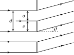 \[d=a+e\]
where a = width of the slit e = opaque part
(4) The condition for formation of bright fringe is \[d\sin \theta =n\lambda ,\]where n = 0, 1, 2, .... is called the order of diffraction.
\[d=a+e\]
where a = width of the slit e = opaque part
(4) The condition for formation of bright fringe is \[d\sin \theta =n\lambda ,\]where n = 0, 1, 2, .... is called the order of diffraction. 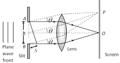 (1) The diffraction pattern consists of a central bright fringe (central maxima) surrounded by dark and bright lines (called secondary minima and maxima).
(2) At point O on the screen, the central maxima is obtained. The wavelets originating from points A and B meets in the same phase at this point, hence at O, intensity is maximum.
(3) Secondary minima : For obtaining nth secondary minima at P on the screen, path difference between the diffracted waves \[\Delta =b\sin \theta =n\lambda \]
(i) Angular position of nth secondary minima \[\sin \theta \approx \theta =\frac{n\lambda }{b}\]
(ii) Distance of nth secondary minima from central maxima
\[{{x}_{n}}=D.\theta =\frac{n\lambda D}{b}=\frac{n\lambda f}{b}\]; where D = Distance between slit and screen. \[f\approx D=\] Focal length of converging lens.
(4) Secondary maxima : For nth secondary maxima at P on the screen.
Path difference \[\Delta =b\sin \theta =(2n+1)\frac{\lambda }{2}\]; where n = 1, 2, 3 .....
(i) Angular position of nth secondary maxima
\[\sin \approx \theta \approx \frac{(2n+1)\lambda }{2b}\]
(ii) Distance of nth secondary maxima from central maxima
\[{{x}_{n}}=D.\theta =\frac{(2n+1)\lambda D}{2b}=\frac{(2n+1)\lambda f}{2b}\]
(5) Central maxima : The central maxima lies between the first minima on both sides.
(1) The diffraction pattern consists of a central bright fringe (central maxima) surrounded by dark and bright lines (called secondary minima and maxima).
(2) At point O on the screen, the central maxima is obtained. The wavelets originating from points A and B meets in the same phase at this point, hence at O, intensity is maximum.
(3) Secondary minima : For obtaining nth secondary minima at P on the screen, path difference between the diffracted waves \[\Delta =b\sin \theta =n\lambda \]
(i) Angular position of nth secondary minima \[\sin \theta \approx \theta =\frac{n\lambda }{b}\]
(ii) Distance of nth secondary minima from central maxima
\[{{x}_{n}}=D.\theta =\frac{n\lambda D}{b}=\frac{n\lambda f}{b}\]; where D = Distance between slit and screen. \[f\approx D=\] Focal length of converging lens.
(4) Secondary maxima : For nth secondary maxima at P on the screen.
Path difference \[\Delta =b\sin \theta =(2n+1)\frac{\lambda }{2}\]; where n = 1, 2, 3 .....
(i) Angular position of nth secondary maxima
\[\sin \approx \theta \approx \frac{(2n+1)\lambda }{2b}\]
(ii) Distance of nth secondary maxima from central maxima
\[{{x}_{n}}=D.\theta =\frac{(2n+1)\lambda D}{2b}=\frac{(2n+1)\lambda f}{2b}\]
(5) Central maxima : The central maxima lies between the first minima on both sides.
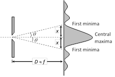 (i) The Angular width d central maxima = \[2\theta =\frac{2\lambda }{b}\]
(ii) Linear width of central maxima \[=2x=2D\theta =2f\theta =\frac{2\lambda f}{b}\]
(6) Intensity distribution : If the intensity of the central maxima is \[{{l}_{0}}\] then the intensity of the first and second secondary maxima are found to be \[\frac{{{I}_{0}}}{22}\] and \[\frac{{{I}_{0}}}{61}\]. Thus diffraction fringes are of unequal width and unequal intensities.
(i) The Angular width d central maxima = \[2\theta =\frac{2\lambda }{b}\]
(ii) Linear width of central maxima \[=2x=2D\theta =2f\theta =\frac{2\lambda f}{b}\]
(6) Intensity distribution : If the intensity of the central maxima is \[{{l}_{0}}\] then the intensity of the first and second secondary maxima are found to be \[\frac{{{I}_{0}}}{22}\] and \[\frac{{{I}_{0}}}{61}\]. Thus diffraction fringes are of unequal width and unequal intensities.
 (i) The mathematical expression for in intensity distribution on the screen is given by
\[l={{I}_{o}}{{\left( \frac{\sin \alpha }{\alpha } \right)}^{2}}\] where \[\alpha \] is just a convenient connection between the angle \[\theta \] that locates a point on the viewing screening and light intensity I.
\[\phi =\] Phase difference between the top and bottom ray from the slit width b.
Also \[\alpha =\frac{1}{2}\varphi =\frac{\pi b}{\lambda }\sin \theta \]
(ii) As the slit width increases (relative to wavelength) the width of the control diffraction maxima decreases; that is, the light undergoes less flaring by the slit. The secondary maxima also decreases in width (and becomes weaker).
(iii) If \[b>>\lambda \], the secondary maxima due to the slit disappear; we then no longer have single slit diffraction.
(iv) When the slit width is reduced by a factor of 2, the amplitude of the wave at the centre more...
(i) The mathematical expression for in intensity distribution on the screen is given by
\[l={{I}_{o}}{{\left( \frac{\sin \alpha }{\alpha } \right)}^{2}}\] where \[\alpha \] is just a convenient connection between the angle \[\theta \] that locates a point on the viewing screening and light intensity I.
\[\phi =\] Phase difference between the top and bottom ray from the slit width b.
Also \[\alpha =\frac{1}{2}\varphi =\frac{\pi b}{\lambda }\sin \theta \]
(ii) As the slit width increases (relative to wavelength) the width of the control diffraction maxima decreases; that is, the light undergoes less flaring by the slit. The secondary maxima also decreases in width (and becomes weaker).
(iii) If \[b>>\lambda \], the secondary maxima due to the slit disappear; we then no longer have single slit diffraction.
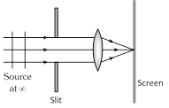
(iv) When the slit width is reduced by a factor of 2, the amplitude of the wave at the centre more... 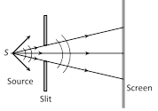 (2) Fraunhofer diffraction : In this case both source and screen are effectively at infinite distance from the diffracting device.
Common examples : Diffraction at single slit, double slit and diffraction grating.
(2) Fraunhofer diffraction : In this case both source and screen are effectively at infinite distance from the diffracting device.
Common examples : Diffraction at single slit, double slit and diffraction grating.


You need to login to perform this action.
You will be redirected in
3 sec

