 (2) Principle : It works on the principle of total internal reflection.
(3) Action : The refractive index of the glass used for making core \[({{\mu }_{1}}\approx 1.7)\] is a little more than the refractive index of the glass \[({{\mu }_{1}}\approx 1.5)\] used for making the cladding i.e. \[{{\mu }_{1}}>{{\mu }_{1}}\].
The core dimension is so small \[(\approx 10\,mm)\] that the light entering will almost essentially be having incident angle \[({{\theta }_{i}})\] more than the critical angle \[({{\theta }_{c}})\] and will suffer total internal reflection at the core. Cladding boundary such successive total reflections at opposite boundaries will confine the light to the core as shown in figure.
(2) Principle : It works on the principle of total internal reflection.
(3) Action : The refractive index of the glass used for making core \[({{\mu }_{1}}\approx 1.7)\] is a little more than the refractive index of the glass \[({{\mu }_{1}}\approx 1.5)\] used for making the cladding i.e. \[{{\mu }_{1}}>{{\mu }_{1}}\].
The core dimension is so small \[(\approx 10\,mm)\] that the light entering will almost essentially be having incident angle \[({{\theta }_{i}})\] more than the critical angle \[({{\theta }_{c}})\] and will suffer total internal reflection at the core. Cladding boundary such successive total reflections at opposite boundaries will confine the light to the core as shown in figure.
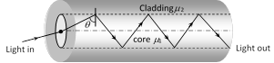 (4) Critical angle \[({{\theta }_{c}})\]: At core-cladding interface if \[\theta ={{\theta }_{c}}\] then \[\cos {{\theta }_{c}}=\frac{\sqrt{\mu _{1}^{2}-\mu _{2}^{2}}}{{{\mu }_{1}}}\]\[\Rightarrow \]\[{{\theta }_{c}}={{\cos }^{-1}}\left( \frac{\sqrt{\mu _{1}^{2}-\mu _{2}^{2}}}{{{\mu }_{1}}} \right)\]
(5) Acceptance angle \[({{\theta }_{a}})\] : The value of maximum angle of incidence with the axis of fibre in air for which all the incident light is totally reflected is known as acceptance angle.
(4) Critical angle \[({{\theta }_{c}})\]: At core-cladding interface if \[\theta ={{\theta }_{c}}\] then \[\cos {{\theta }_{c}}=\frac{\sqrt{\mu _{1}^{2}-\mu _{2}^{2}}}{{{\mu }_{1}}}\]\[\Rightarrow \]\[{{\theta }_{c}}={{\cos }^{-1}}\left( \frac{\sqrt{\mu _{1}^{2}-\mu _{2}^{2}}}{{{\mu }_{1}}} \right)\]
(5) Acceptance angle \[({{\theta }_{a}})\] : The value of maximum angle of incidence with the axis of fibre in air for which all the incident light is totally reflected is known as acceptance angle.
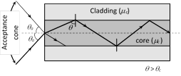 If \[{{\theta }_{a}}=\] Acceptance angle then \[{{\mu }_{1}}=\] refractive index of core, \[{{\mu }_{2}}=\] refractive index of cladding. \[\sin {{\theta }_{a}}=\frac{\sqrt{\mu _{1}^{2}-\mu _{2}^{2}}}{{{\mu }_{0}}}\]\[\Rightarrow \]\[{{\theta }_{a}}={{\sin }^{-1}}\sqrt{\mu _{1}^{2}-\mu _{2}^{2}}\] (for air \[{{\mu }_{0}}=1\])
(6) Numerical aperture : Light gathering capability of a fibre is related to numerical aperture. This is defined as the sine of acceptance angle i.e. \[NA=\sin i=\sqrt{\mu _{1}^{2}-\mu _{2}^{2}}\]
The numerical aperture can also be given in terms of relative core-cladding index difference \[(\Delta )\], where \[\Delta =\frac{\mu _{1}^{2}-\mu _{2}^{2}}{2\mu _{1}^{2}}\]
Thus, \[NA=\sqrt{\mu _{1}^{2}-\mu _{2}^{2}}={{\mu }_{1}}\sqrt{2\Delta }\]
(7) Fibre attenuation : In practice a very small part of light energy is lost from an optical fibre. This reduction in energy of the light is called attenuation and is described by \[I={{I}_{0}}{{e}^{-\alpha x}}\]
where \[{{I}_{0}}=\] Intensity of light when it enters the fibre
\[I=\] Intensity of light at a distance x along the fibre
\[\alpha =\] Absorption co-efficient or attenuation co-efficient
Also attenuation (in dB) \[=10{{\log }_{10}}\frac{I}{{{I}_{0}}}\]
(8) Types of optical fibre
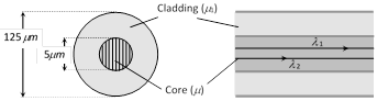
(i) Monomode optical fibre : It has a very narrow core of diameter about \[5\,\mu m\] or less, cladding is relatively big.
If \[{{\theta }_{a}}=\] Acceptance angle then \[{{\mu }_{1}}=\] refractive index of core, \[{{\mu }_{2}}=\] refractive index of cladding. \[\sin {{\theta }_{a}}=\frac{\sqrt{\mu _{1}^{2}-\mu _{2}^{2}}}{{{\mu }_{0}}}\]\[\Rightarrow \]\[{{\theta }_{a}}={{\sin }^{-1}}\sqrt{\mu _{1}^{2}-\mu _{2}^{2}}\] (for air \[{{\mu }_{0}}=1\])
(6) Numerical aperture : Light gathering capability of a fibre is related to numerical aperture. This is defined as the sine of acceptance angle i.e. \[NA=\sin i=\sqrt{\mu _{1}^{2}-\mu _{2}^{2}}\]
The numerical aperture can also be given in terms of relative core-cladding index difference \[(\Delta )\], where \[\Delta =\frac{\mu _{1}^{2}-\mu _{2}^{2}}{2\mu _{1}^{2}}\]
Thus, \[NA=\sqrt{\mu _{1}^{2}-\mu _{2}^{2}}={{\mu }_{1}}\sqrt{2\Delta }\]
(7) Fibre attenuation : In practice a very small part of light energy is lost from an optical fibre. This reduction in energy of the light is called attenuation and is described by \[I={{I}_{0}}{{e}^{-\alpha x}}\]
where \[{{I}_{0}}=\] Intensity of light when it enters the fibre
\[I=\] Intensity of light at a distance x along the fibre
\[\alpha =\] Absorption co-efficient or attenuation co-efficient
Also attenuation (in dB) \[=10{{\log }_{10}}\frac{I}{{{I}_{0}}}\]
(8) Types of optical fibre
(i) Monomode optical fibre : It has a very narrow core of diameter about \[5\,\mu m\] or less, cladding is relatively big.
 (ii) Multimode optical fibre : It is again of two types
(a) Step index multimode fibre :
The diameter of the core is about \[50\,\mu m\]
Core has constant R.I \[{{\mu }_{1}}\] from it's centre to boundary.
The refractive index then changes to a lower value of \[{{\mu }_{2}}\], which remains constant through the cladding.
(ii) Multimode optical fibre : It is again of two types
(a) Step index multimode fibre :
The diameter of the core is about \[50\,\mu m\]
Core has constant R.I \[{{\mu }_{1}}\] from it's centre to boundary.
The refractive index then changes to a lower value of \[{{\mu }_{2}}\], which remains constant through the cladding.
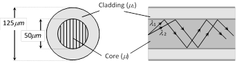 Since refractive index of a material depend on the wavelength of light. The wavelength more...
 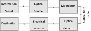 (5) Light emitting diodes (LED) and diode lasers are preferred for optical source. LED's are used for small distance transmission while diode laser is used for very large distance transmission.
(6) In order to transmit information signal via an optical communication system, it is necessary to modulate light with the information signal.
(7) The optical signal reaching the receiving end has to be detected by a detector which converts light into electrical signals, So that the transmitted information may be decoded. Semiconductor based photo-electors are used
(5) Light emitting diodes (LED) and diode lasers are preferred for optical source. LED's are used for small distance transmission while diode laser is used for very large distance transmission.
(6) In order to transmit information signal via an optical communication system, it is necessary to modulate light with the information signal.
(7) The optical signal reaching the receiving end has to be detected by a detector which converts light into electrical signals, So that the transmitted information may be decoded. Semiconductor based photo-electors are used 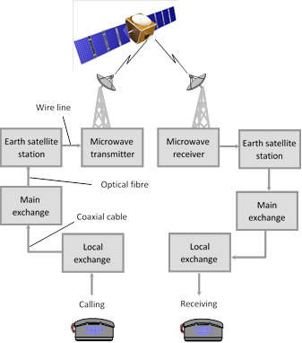
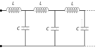
 (1) Such inductors, resistors and capacitors are distributed throughout the transmission line. As a result each length of transmission line has a characteristic impedance.
(2) In case of co-axial cable, the dielectric can be represented by a shunt resistance G.
(3) When co-axial cable is used to transmit a radio frequency signal, \[{{X}_{L}}\] and \[{{X}_{C}}\] are large as compared to R and G respectively. Hence R and G can be neglected.
(1) Such inductors, resistors and capacitors are distributed throughout the transmission line. As a result each length of transmission line has a characteristic impedance.
(2) In case of co-axial cable, the dielectric can be represented by a shunt resistance G.
(3) When co-axial cable is used to transmit a radio frequency signal, \[{{X}_{L}}\] and \[{{X}_{C}}\] are large as compared to R and G respectively. Hence R and G can be neglected.
 (4) In co-axial cable, R is zero, so no loss of energy and hence no attenuation of frequency signal occurs when transmitted along it. That's why co-axial cables are specially used in cable TV network.
(5) Characteristic impedance \[({{Z}_{0}})\] : It is defined as the impedance measured at the input of a line of infinite length.
For parallel line \[{{Z}_{0}}=\frac{276}{\sqrt{k}}\log \frac{2s}{d}\]
(4) In co-axial cable, R is zero, so no loss of energy and hence no attenuation of frequency signal occurs when transmitted along it. That's why co-axial cables are specially used in cable TV network.
(5) Characteristic impedance \[({{Z}_{0}})\] : It is defined as the impedance measured at the input of a line of infinite length.
For parallel line \[{{Z}_{0}}=\frac{276}{\sqrt{k}}\log \frac{2s}{d}\]
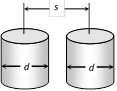 d = Diameter of each wire
s = Separation between the two wires
k = Dielectric constant of the insulating medium
For co-axial line wire \[{{Z}_{0}}=\frac{138}{\sqrt{k}}\log \frac{D}{d}\]
d = Diameter of each wire
s = Separation between the two wires
k = Dielectric constant of the insulating medium
For co-axial line wire \[{{Z}_{0}}=\frac{138}{\sqrt{k}}\log \frac{D}{d}\]
 d = Diameter of inner conductor
D = Diameter of outer conductor
At radio frequency \[{{Z}_{0}}=\sqrt{\frac{L}{C}}\]
the usual range of characteristic impedance for parallel wire lines is \[150\,\Omega \] to \[600\,\Omega \] and for co-axial wire it is \[40\,\Omega \] to \[150\,\Omega \].
(6) Velocity factor of a line (v. f.) : It is the ratio of reduction of speed of light in the dielectric of the cable
\[v.f.=\frac{v}{c}=\frac{\text{Speed of light in medium}}{\text{Speed of light in vacuum}}=\frac{1}{\sqrt{K}}\]
For a line v.f. is generally of the order of 0.6 to 0.9.
d = Diameter of inner conductor
D = Diameter of outer conductor
At radio frequency \[{{Z}_{0}}=\sqrt{\frac{L}{C}}\]
the usual range of characteristic impedance for parallel wire lines is \[150\,\Omega \] to \[600\,\Omega \] and for co-axial wire it is \[40\,\Omega \] to \[150\,\Omega \].
(6) Velocity factor of a line (v. f.) : It is the ratio of reduction of speed of light in the dielectric of the cable
\[v.f.=\frac{v}{c}=\frac{\text{Speed of light in medium}}{\text{Speed of light in vacuum}}=\frac{1}{\sqrt{K}}\]
For a line v.f. is generally of the order of 0.6 to 0.9. 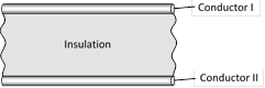 (i) The wires may be hard or flexible depending on the power to be handled.
(ii) It is commonly used to connect an anteena with TV receiver.
(iii) Such wires can suffer from interferences and losses.
(2) Twisted pair wire : It consists of two insulated copper wires twisted around each other at regular intervals to minimize electrical interference.
(i) Twisted pair wires are used to connect telephone systems. It works well up to a distance of about 10 cm. They cannot transmit signals over very large distances.
(i) The wires may be hard or flexible depending on the power to be handled.
(ii) It is commonly used to connect an anteena with TV receiver.
(iii) Such wires can suffer from interferences and losses.
(2) Twisted pair wire : It consists of two insulated copper wires twisted around each other at regular intervals to minimize electrical interference.
(i) Twisted pair wires are used to connect telephone systems. It works well up to a distance of about 10 cm. They cannot transmit signals over very large distances.
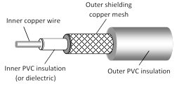 (i) Co-axial line wires can be used for microwaves and ultra high frequency waves.
(ii) The communication through co-axial lines is more efficient than through a twisted pair wire lines.
(iii) Co-axial cables can be gas filled also. To reduce flash over between the conductor handling high power, N2-gas is used in the cable.
(i) Co-axial line wires can be used for microwaves and ultra high frequency waves.
(ii) The communication through co-axial lines is more efficient than through a twisted pair wire lines.
(iii) Co-axial cables can be gas filled also. To reduce flash over between the conductor handling high power, N2-gas is used in the cable. 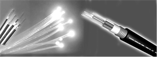 Line communication means interconnection of two points that are at some distance from each other with the help of wires for exchange of information e.g. interconnection between a transmitter and receiver or a transmitter and anteena or an anteena and receiver.
 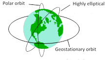 (3) A remote sensing satellite takes, photographs of a particular region which nearly the same illumination every time it passes through that region.
(4) The most useful remote sensing technology is that it makes possible the repetitive surveys of vast areas in a very short time, even if the areas are inaccessible.
(5) Space based remote sensing is a new technology. It has high potential for applications in nearly all aspects of resource management.
(6) The Indian remote sensing satellites are IRS-1A, JRS-1B, and IRS-1C.
(7) Some applications of remote sensing includes
(i) Meteorology : (development of weather systems and weather for casting).
(ii) Climatology : Monitoring climatic changes.
(iii) Oceanography : (Sea surface temperatures, mapping of sea-ice and oil pollution monitoring).
(iv) Archaeology, geological surveys.
(v) Water resource surveys,
(vi) Urban land use surveys.
(vii) Agriculture and forestry and natural disaster.
(viii) In the field of spying to detect movements of enemy army an their positions.
(ix) It is used to locate the place where under ground nuclear explosion has carried out.
(3) A remote sensing satellite takes, photographs of a particular region which nearly the same illumination every time it passes through that region.
(4) The most useful remote sensing technology is that it makes possible the repetitive surveys of vast areas in a very short time, even if the areas are inaccessible.
(5) Space based remote sensing is a new technology. It has high potential for applications in nearly all aspects of resource management.
(6) The Indian remote sensing satellites are IRS-1A, JRS-1B, and IRS-1C.
(7) Some applications of remote sensing includes
(i) Meteorology : (development of weather systems and weather for casting).
(ii) Climatology : Monitoring climatic changes.
(iii) Oceanography : (Sea surface temperatures, mapping of sea-ice and oil pollution monitoring).
(iv) Archaeology, geological surveys.
(v) Water resource surveys,
(vi) Urban land use surveys.
(vii) Agriculture and forestry and natural disaster.
(viii) In the field of spying to detect movements of enemy army an their positions.
(ix) It is used to locate the place where under ground nuclear explosion has carried out. 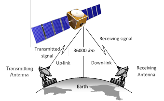 (2) Satellite communication is mainly done through geostationary satellites (for steady reliable transmission and reception)
(3) A geostationary satellite has the same time period of revolution of earth (i.e. 24 hrs.). It appears stationary w.r.t. earth. It locates at the height of 36000 km above the earth's surface (well above the ionosphere).
(4) A communication satellite is a spacecraft placed in an orbit around the earth which carriers a transmitting and receiving equipment called radio transponder. It amplifies the microwave signals emitted by the transmitter from the surface of earth and send then to the receiving station on earth.
(5) The transmitted signal is UP-LINKED and received by the satellite station which DOWN-LINKS it with the ground station through it's transmitter.
The up-link and down-link frequencies are kept different (both frequencies being in the regions of UHF/microwave).
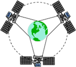
(6) A single satellite cannot cover the entire surface of the earth. At least three geo-stationary satellites are required which are 120° apart from each other to have the communication link over the entire globe of earth.
(2) Satellite communication is mainly done through geostationary satellites (for steady reliable transmission and reception)
(3) A geostationary satellite has the same time period of revolution of earth (i.e. 24 hrs.). It appears stationary w.r.t. earth. It locates at the height of 36000 km above the earth's surface (well above the ionosphere).
(4) A communication satellite is a spacecraft placed in an orbit around the earth which carriers a transmitting and receiving equipment called radio transponder. It amplifies the microwave signals emitted by the transmitter from the surface of earth and send then to the receiving station on earth.
(5) The transmitted signal is UP-LINKED and received by the satellite station which DOWN-LINKS it with the ground station through it's transmitter.
The up-link and down-link frequencies are kept different (both frequencies being in the regions of UHF/microwave).
(6) A single satellite cannot cover the entire surface of the earth. At least three geo-stationary satellites are required which are 120° apart from each other to have the communication link over the entire globe of earth.
 (7) Satellite technology is very useful in collecting information about various factors of the atmosphere which governs the weather and climatic conditions.
The satellite communication can be used for establishing mobile communication with great use the communication satellites are now being used in Global Positioning System (GPS). The ordinary users can find their positions within an accuracy of 100m.
There are two types of satellites used for long distance transmission.
(i) Passive satellite : It act as reflector only for the signals transmitted from earth. Moon the natural satellite of earth is a passive satellite.
(ii) Active satellite : It carries all the equipment used for receiving signals sent from the earth, processing them and then re-transmitting them to the earth. Now a days active satellites are in use.
(8) The Indian communication satellites INSAT-2B and INSAT-2C are positioned in such away in the outer space that they are accessible from any place in India.
(7) Satellite technology is very useful in collecting information about various factors of the atmosphere which governs the weather and climatic conditions.
The satellite communication can be used for establishing mobile communication with great use the communication satellites are now being used in Global Positioning System (GPS). The ordinary users can find their positions within an accuracy of 100m.
There are two types of satellites used for long distance transmission.
(i) Passive satellite : It act as reflector only for the signals transmitted from earth. Moon the natural satellite of earth is a passive satellite.
(ii) Active satellite : It carries all the equipment used for receiving signals sent from the earth, processing them and then re-transmitting them to the earth. Now a days active satellites are in use.
(8) The Indian communication satellites INSAT-2B and INSAT-2C are positioned in such away in the outer space that they are accessible from any place in India. 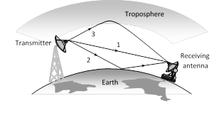 The space wave propagation is also called as line of sight propagation. The line of sight distance is the distance between transmitting antenna and receiving antenna at which they can see each other.
Space wave propagation can be utilised for transmitting high frequency TV and FM signals.
(1) Television signal propagation : Frequency range for propagation is 80 MHz to 200 MHz
Height of transmitting antenna : \[h=\frac{{{d}^{2}}}{2R}\] (d = distance covered by the signal, R = Radius of the Earth)
Area covered : \[A=\pi {{d}^{2}}=2\,\pi Rh\]
Population cover : Population density ´ Area covered
(2) Microwave communication : Microwave communication systems are used for long distance communication. Since at microwave frequencies, electromagnetic waves cannot bend across the obstacles, such as the top of the buildings, mountains etc., it is therefore necessary that microwave transmission is in line-of-sight.
The space wave propagation is also called as line of sight propagation. The line of sight distance is the distance between transmitting antenna and receiving antenna at which they can see each other.
Space wave propagation can be utilised for transmitting high frequency TV and FM signals.
(1) Television signal propagation : Frequency range for propagation is 80 MHz to 200 MHz
Height of transmitting antenna : \[h=\frac{{{d}^{2}}}{2R}\] (d = distance covered by the signal, R = Radius of the Earth)
Area covered : \[A=\pi {{d}^{2}}=2\,\pi Rh\]
Population cover : Population density ´ Area covered
(2) Microwave communication : Microwave communication systems are used for long distance communication. Since at microwave frequencies, electromagnetic waves cannot bend across the obstacles, such as the top of the buildings, mountains etc., it is therefore necessary that microwave transmission is in line-of-sight.
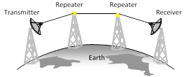 Due to curvature in the surface of earth, the range of microwave transmission is very small \[(\approx 50\,\,km)\]. The range of microwave transmission is also limited by the fact that signals gets weaker and weaker as it propagates. However, these problems are overcome by using repeaters (A repeater is basically an amplifier, which amplifies the attenuated signal and then retransmits it.) at intervals between the transmitter and the receiver. Due to this, the cost of transmission of signal between the two stations increases.
The problems faced in a microwave communication system are solved to a large extent by using a geostationary satellite as a communication satellite.
Due to curvature in the surface of earth, the range of microwave transmission is very small \[(\approx 50\,\,km)\]. The range of microwave transmission is also limited by the fact that signals gets weaker and weaker as it propagates. However, these problems are overcome by using repeaters (A repeater is basically an amplifier, which amplifies the attenuated signal and then retransmits it.) at intervals between the transmitter and the receiver. Due to this, the cost of transmission of signal between the two stations increases.
The problems faced in a microwave communication system are solved to a large extent by using a geostationary satellite as a communication satellite. 


You need to login to perform this action.
You will be redirected in
3 sec

