
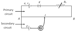
 J = Jockey
K = Key
R = Resistance of potentiometer wire,
\[\rho =\] Specific resistance of potentiometer wire.
\[{{R}_{h}}=\] Variable resistance which controls the current through the wire AB
(i) The specific resistance \[(\rho )\] of potentiometer wire must be high but its temperature coefficient of resistance \[(\alpha )\] must be low.
(ii) All higher potential points (terminals) of primary and secondary circuits must be connected together at point A and all lower potential points must be connected to point B or jockey.
(iii) The value of known potential difference must be greater than the value of unknown potential difference to be measured.
(iv) The potential gradient must remain constant. For this the current in the primary circuit must remain constant and the jockey must not be slided in contact with the wire.
(v) The diameter of potentiometer wire must be uniform everywhere.
(2) Potential gradient (x) : Potential difference (or fall in potential) per unit length of wire is called potential gradient i.e. \[x=\frac{V}{L}\frac{volt}{m}\] where \[V=iR=\left( \frac{e}{R+{{R}_{h}}+r} \right).R\].
So \[x=\frac{V}{L}=\frac{iR}{L}=\frac{i\rho }{A}=\frac{e}{\mathbf{(}R+{{R}_{h}}+r\mathbf{)}}.\frac{R}{L}\]
(i) Potential gradient directly depends upon
(a) The resistance per unit length (R/L) of potentiometer wire.
(b) The radius of potentiometer wire (i.e. Area of cross-section)
(c) The specific resistance of the material of potentiometer wire (i.e. \[\rho \])
(d) The current flowing through potentiometer wire (i)
(ii) potential gradient indirectly depends upon
(a) The emf of battery in the primary circuit (i.e. e)
(b) The resistance of rheostat in the primary circuit (i.e. \[{{R}_{h}}\])
(3) Working : Suppose jocky is made to touch a point J on wire then potential difference between A and J will be \[V=xl\]
At this length (l) two potential difference are obtained
(i) V due to battery e and
(ii) E due to unknown cell
J = Jockey
K = Key
R = Resistance of potentiometer wire,
\[\rho =\] Specific resistance of potentiometer wire.
\[{{R}_{h}}=\] Variable resistance which controls the current through the wire AB
(i) The specific resistance \[(\rho )\] of potentiometer wire must be high but its temperature coefficient of resistance \[(\alpha )\] must be low.
(ii) All higher potential points (terminals) of primary and secondary circuits must be connected together at point A and all lower potential points must be connected to point B or jockey.
(iii) The value of known potential difference must be greater than the value of unknown potential difference to be measured.
(iv) The potential gradient must remain constant. For this the current in the primary circuit must remain constant and the jockey must not be slided in contact with the wire.
(v) The diameter of potentiometer wire must be uniform everywhere.
(2) Potential gradient (x) : Potential difference (or fall in potential) per unit length of wire is called potential gradient i.e. \[x=\frac{V}{L}\frac{volt}{m}\] where \[V=iR=\left( \frac{e}{R+{{R}_{h}}+r} \right).R\].
So \[x=\frac{V}{L}=\frac{iR}{L}=\frac{i\rho }{A}=\frac{e}{\mathbf{(}R+{{R}_{h}}+r\mathbf{)}}.\frac{R}{L}\]
(i) Potential gradient directly depends upon
(a) The resistance per unit length (R/L) of potentiometer wire.
(b) The radius of potentiometer wire (i.e. Area of cross-section)
(c) The specific resistance of the material of potentiometer wire (i.e. \[\rho \])
(d) The current flowing through potentiometer wire (i)
(ii) potential gradient indirectly depends upon
(a) The emf of battery in the primary circuit (i.e. e)
(b) The resistance of rheostat in the primary circuit (i.e. \[{{R}_{h}}\])
(3) Working : Suppose jocky is made to touch a point J on wire then potential difference between A and J will be \[V=xl\]
At this length (l) two potential difference are obtained
(i) V due to battery e and
(ii) E due to unknown cell
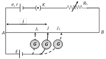 If V > E then current will flow in galvanometer circuit in one direction
  If V < E then current will flow in galvanometer circuit in opposite direction
  If V = E then no current will flow in galvanometer circuit this condition to known as null more...
 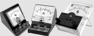 (1) Galvanometer : It is an instrument used to detect small current passing through it by showing deflection. Galvanometers are of different types e.g. moving coil galvanometer, moving magnet galvanometer, hot wire galvanometer. In dc circuit usually moving coil galvanometer are used.
(i) It's symbol :
(1) Galvanometer : It is an instrument used to detect small current passing through it by showing deflection. Galvanometers are of different types e.g. moving coil galvanometer, moving magnet galvanometer, hot wire galvanometer. In dc circuit usually moving coil galvanometer are used.
(i) It's symbol :  where G is the total internal resistance of the galvanometer.
(ii) Full scale deflection current : The current required for full scale deflection in a galvanometer is called full scale deflection current and is represented by \[{{i}_{g}}\].
(iii) Shunt : The small resistance connected in parallel to galvanometer coil, in order to control current flowing through the galvanometer is known as shunt.
Merits and demerits of shunt
where G is the total internal resistance of the galvanometer.
(ii) Full scale deflection current : The current required for full scale deflection in a galvanometer is called full scale deflection current and is represented by \[{{i}_{g}}\].
(iii) Shunt : The small resistance connected in parallel to galvanometer coil, in order to control current flowing through the galvanometer is known as shunt.
Merits and demerits of shunt
| Merits of shunt | Demerits of shunt |
| To protect the galvanometer coil from burning | Shunt resistance decreases the sensitivity of galvanometer. |
| It can be used to convert any galvanometer into ammeter of desired range. |
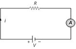 (i) The reading of an ammeter is always lesser than actual current in the circuit.
(ii) Smaller the resistance of an ammeter more accurate will be its reading. An ammeter is said to be ideal if its resistance r is zero.
(iii) Conversion of galvanometer into ammeter : A galvanometer may be converted into an ammeter by connecting a low resistance (called shunt S) in parallel to the galvanometer G as shown in figure.
(i) The reading of an ammeter is always lesser than actual current in the circuit.
(ii) Smaller the resistance of an ammeter more accurate will be its reading. An ammeter is said to be ideal if its resistance r is zero.
(iii) Conversion of galvanometer into ammeter : A galvanometer may be converted into an ammeter by connecting a low resistance (called shunt S) in parallel to the galvanometer G as shown in figure.
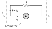 (a) Equivalent resistance of the combination \[=\frac{GS}{G+S}\]
(b) G and S are parallel to each other hence both will have equal potential difference i.e. \[{{i}_{g}}G=(i-{{i}_{g}})S\]; which gives
Required shunt \[S=\frac{{{i}_{g}}}{\mathbf{(}i-{{i}_{g}}\mathbf{)}}G\]
(c) To pass nth part of main current (i.e. \[{{i}_{g}}=\frac{i}{n}\]) through the galvanometer, required shunt \[S=\frac{G}{\mathbf{(}n-\mathbf{1)}}\].
(3) Voltmeter : It is a device used to measure potential difference and is always put in parallel with the 'circuit element' across which potential difference is to be measured.
(a) Equivalent resistance of the combination \[=\frac{GS}{G+S}\]
(b) G and S are parallel to each other hence both will have equal potential difference i.e. \[{{i}_{g}}G=(i-{{i}_{g}})S\]; which gives
Required shunt \[S=\frac{{{i}_{g}}}{\mathbf{(}i-{{i}_{g}}\mathbf{)}}G\]
(c) To pass nth part of main current (i.e. \[{{i}_{g}}=\frac{i}{n}\]) through the galvanometer, required shunt \[S=\frac{G}{\mathbf{(}n-\mathbf{1)}}\].
(3) Voltmeter : It is a device used to measure potential difference and is always put in parallel with the 'circuit element' across which potential difference is to be measured.
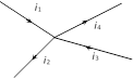 In a circuit, at any junction the sum of the currents entering the junction must equal the sum of the currents leaving the junction. \[{{i}_{1}}+{{i}_{3}}={{i}_{2}}+{{i}_{4}}\]
(ii) This law is simply a statement of "conservation of charge".
(2) Kirchoff's second law : This law is also known as loop rule or voltage law (KVL) and according to it 'the algebraic sum of the changes in potential in complete traversal of a mesh (closed loop) is zero', i.e. \[\Sigma V=0\]
(i) This law represents "conservation of energy".
(ii) If there are n meshes in a circuit, the number of independent equations in accordance with loop rule will be \[(n-1)\].
(3) Sign convention for the application of Kirchoff's law : For the application of Kirchoff's laws following sign convention are to be considered
(i) The change in potential in traversing a resistance in the direction of current is \[-iR\] while in the opposite direction \[+iR\]
In a circuit, at any junction the sum of the currents entering the junction must equal the sum of the currents leaving the junction. \[{{i}_{1}}+{{i}_{3}}={{i}_{2}}+{{i}_{4}}\]
(ii) This law is simply a statement of "conservation of charge".
(2) Kirchoff's second law : This law is also known as loop rule or voltage law (KVL) and according to it 'the algebraic sum of the changes in potential in complete traversal of a mesh (closed loop) is zero', i.e. \[\Sigma V=0\]
(i) This law represents "conservation of energy".
(ii) If there are n meshes in a circuit, the number of independent equations in accordance with loop rule will be \[(n-1)\].
(3) Sign convention for the application of Kirchoff's law : For the application of Kirchoff's laws following sign convention are to be considered
(i) The change in potential in traversing a resistance in the direction of current is \[-iR\] while in the opposite direction \[+iR\]
 (ii) The change in potential in traversing an emf source from negative to positive terminal is \[+E\] while in the opposite direction \[-E\] irrespective of the direction of current in the circuit.
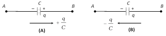
 (iii) The change in potential in traversing a capacitor from the negative terminal to the positive terminal is \[+\frac{q}{C}\] while in opposite direction \[-\frac{q}{C}\].
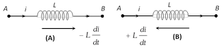
 (iv) The change in voltage in traversing an inductor in the direction of current is \[-L\frac{di}{dt}\] while in opposite direction it is \[+L\frac{di}{dt}\].
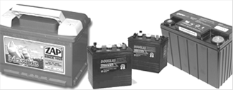 Group of cell is called a battery.
In series grouping of cell's their emf's are additive or subtractive while their internal resistances are always additive. If dissimilar plates of cells are connected together their emf's are added to each other while if their similar plates are connected together their emf's are subtractive.
Group of cell is called a battery.
In series grouping of cell's their emf's are additive or subtractive while their internal resistances are always additive. If dissimilar plates of cells are connected together their emf's are added to each other while if their similar plates are connected together their emf's are subtractive.
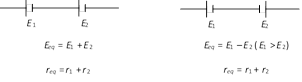 (1) Series grouping : In series grouping anode of one cell is connected to cathode of other cell and so on. If n identical cells are connected in series
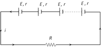 (i) Equivalent emf of the combination \[{{E}_{eq}}=nE\]
(ii) Equivalent internal resistance \[{{r}_{eq}}=nr\]
(iii) Main current = Current from each cell \[=i=\frac{nE}{R+nr}\]
(iv) Potential difference across external resistance \[V=iR\]
(v) Potential difference across each cell \[V'=\frac{V}{n}\]
(vi) Power dissipated in the external circuit \[={{\left( \frac{nE}{R+nr} \right)}^{2}}.\,R\]
(vii) Condition for maximum power \[R=nr\] and \[{{P}_{\max }}=n\,\left( \frac{{{E}^{2}}}{4r} \right)\]
(viii) This type of combination is used when \[nr<<R\].
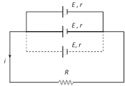
(2) Parallel grouping : In parallel grouping all anodes are connected at one point and all cathode are connected together at other point. If n identical cells are connected in parallel
(i) Equivalent emf of the combination \[{{E}_{eq}}=nE\]
(ii) Equivalent internal resistance \[{{r}_{eq}}=nr\]
(iii) Main current = Current from each cell \[=i=\frac{nE}{R+nr}\]
(iv) Potential difference across external resistance \[V=iR\]
(v) Potential difference across each cell \[V'=\frac{V}{n}\]
(vi) Power dissipated in the external circuit \[={{\left( \frac{nE}{R+nr} \right)}^{2}}.\,R\]
(vii) Condition for maximum power \[R=nr\] and \[{{P}_{\max }}=n\,\left( \frac{{{E}^{2}}}{4r} \right)\]
(viii) This type of combination is used when \[nr<<R\].
(2) Parallel grouping : In parallel grouping all anodes are connected at one point and all cathode are connected together at other point. If n identical cells are connected in parallel
 (i) Equivalent emf \[{{E}_{eq}}=E\]
(ii) Equivalent internal resistance \[{{R}_{eq}}=r/n\]
(iii) Main current \[i=\frac{E}{R+r/n}\]
(iv) potential difference across external resistance = p.d. across each cell \[=V=iR\]
(v) Current from each cell \[i'=\frac{i}{n}\]
(vi) Power dissipated in the circuit \[P={{\left( \frac{E}{R+r/n} \right)}^{2}}.\,R\]
(vii) Condition for max. power is \[R=r/n\] and \[{{P}_{\max }}=n\,\left( \frac{{{E}^{2}}}{4r} \right)\]
(viii) This type of combination is used when \[nr>>R\]
(3) Mixed Grouping : If n identical cell's are connected in a row and such m row's are connected in parallel as shown.
(i) Equivalent emf \[{{E}_{eq}}=E\]
(ii) Equivalent internal resistance \[{{R}_{eq}}=r/n\]
(iii) Main current \[i=\frac{E}{R+r/n}\]
(iv) potential difference across external resistance = p.d. across each cell \[=V=iR\]
(v) Current from each cell \[i'=\frac{i}{n}\]
(vi) Power dissipated in the circuit \[P={{\left( \frac{E}{R+r/n} \right)}^{2}}.\,R\]
(vii) Condition for max. power is \[R=r/n\] and \[{{P}_{\max }}=n\,\left( \frac{{{E}^{2}}}{4r} \right)\]
(viii) This type of combination is used when \[nr>>R\]
(3) Mixed Grouping : If n identical cell's are connected in a row and such m row's are connected in parallel as shown.
 (i) Equivalent emf of the combination\[{{E}_{eq}}=nE\]
(ii) Equivalent internal resistance of the combination \[{{r}_{eq}}=\frac{nr}{m}\]
(iii) Main current flowing through the load \[i=\frac{nE}{R+\frac{nr}{m}}=\frac{mnE}{mR+nr}\]
(iv) Potential difference across load \[V=iR\]
(v) Potential difference across each cell \[V'=\frac{V}{n}\]
(vi) Current from each cell \[i\,'=\frac{i}{n}\]
(vii) Condition for maximum power \[R=\frac{nr}{m}\] and\[{{P}_{\max }}=(mn)\frac{{{E}^{2}}}{4r}\]
(viii) Total number of cell \[=mn\]
(i) Equivalent emf of the combination\[{{E}_{eq}}=nE\]
(ii) Equivalent internal resistance of the combination \[{{r}_{eq}}=\frac{nr}{m}\]
(iii) Main current flowing through the load \[i=\frac{nE}{R+\frac{nr}{m}}=\frac{mnE}{mR+nr}\]
(iv) Potential difference across load \[V=iR\]
(v) Potential difference across each cell \[V'=\frac{V}{n}\]
(vi) Current from each cell \[i\,'=\frac{i}{n}\]
(vii) Condition for maximum power \[R=\frac{nr}{m}\] and\[{{P}_{\max }}=(mn)\frac{{{E}^{2}}}{4r}\]
(viii) Total number of cell \[=mn\] 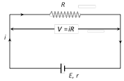 (i) Current given by the cell \[i=\frac{E}{R+r}\]
(ii) Potential difference across the resistance \[V=iR\]
(iii) Potential drop inside the cell \[=ir\]
(iv) Equation of cell \[E=V+ir\]\[(E>V)\]
(v) Internal resistance of the cell \[r=\left( \frac{E}{V}-1 \right)\,\cdot R\]
(vi) Power dissipated in external resistance (load)
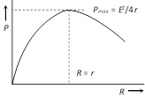
\[P=Vi={{i}^{2}}R=\frac{{{V}^{2}}}{R}={{\left( \frac{E}{R+r} \right)}^{2}}.R\]
Power delivered will be maximum when \[R=r\] so \[{{P}_{\max }}=\frac{{{E}^{2}}}{4r}\].
This statement in generalised from is called "maximum power transfer theorem".
(i) Current given by the cell \[i=\frac{E}{R+r}\]
(ii) Potential difference across the resistance \[V=iR\]
(iii) Potential drop inside the cell \[=ir\]
(iv) Equation of cell \[E=V+ir\]\[(E>V)\]
(v) Internal resistance of the cell \[r=\left( \frac{E}{V}-1 \right)\,\cdot R\]
(vi) Power dissipated in external resistance (load)
\[P=Vi={{i}^{2}}R=\frac{{{V}^{2}}}{R}={{\left( \frac{E}{R+r} \right)}^{2}}.R\]
Power delivered will be maximum when \[R=r\] so \[{{P}_{\max }}=\frac{{{E}^{2}}}{4r}\].
This statement in generalised from is called "maximum power transfer theorem".
 (vii) When the cell is being charged i.e. current is given to the cell then \[E=V-ir\] and \[E<V\].
(2) Open circuit : When no current is taken from the cell it is said to be in open circuit
(vii) When the cell is being charged i.e. current is given to the cell then \[E=V-ir\] and \[E<V\].
(2) Open circuit : When no current is taken from the cell it is said to be in open circuit
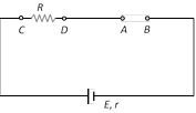 (i) Current through the circuit \[i=0\]
(ii) Potential difference between A and B, \[{{V}_{AB}}=E\]
(iii) Potential difference between C and D, \[{{V}_{CD}}=0\]
(3) Short circuit : If two terminals of cell are join together by a thick conducting wire
(i) Current through the circuit \[i=0\]
(ii) Potential difference between A and B, \[{{V}_{AB}}=E\]
(iii) Potential difference between C and D, \[{{V}_{CD}}=0\]
(3) Short circuit : If two terminals of cell are join together by a thick conducting wire
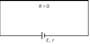 (i) Maximum current (called short circuit current) flows momentarily \[{{i}_{sc}}=\frac{E}{r}\]
(ii) Potential difference V = 0
(i) Maximum current (called short circuit current) flows momentarily \[{{i}_{sc}}=\frac{E}{r}\]
(ii) Potential difference V = 0 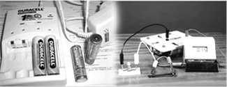 The device which converts chemical energy into electrical energy is known as electric cell. Cell is a source of constant emf but not constant current.
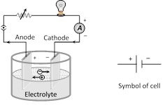 (1) Emf of cell (E) : The potential difference across the terminals of a cell when it is not supplying any current is called it's emf.
(2) Potential difference (V) : The voltage across the terminals of a cell when it is supplying current to external resistance is called potential difference or terminal voltage. Potential difference is equal to the product of current and resistance of that given part i.e. \[V=iR\].
(3) Internal resistance (r) : In case of a cell the opposition of electrolyte to the flow of current through it is called internal resistance of the cell. The internal resistance of a cell depends on the distance between electrodes \[(r\propto d),\] area of electrodes \[[r\propto (1/A)]\] and nature, concentration \[(r\propto C)\] and temperature of electrolyte \[[r\propto (1/temp.)]\].
A cell is said to be ideal, if it has zero internal resistance.
(1) Emf of cell (E) : The potential difference across the terminals of a cell when it is not supplying any current is called it's emf.
(2) Potential difference (V) : The voltage across the terminals of a cell when it is supplying current to external resistance is called potential difference or terminal voltage. Potential difference is equal to the product of current and resistance of that given part i.e. \[V=iR\].
(3) Internal resistance (r) : In case of a cell the opposition of electrolyte to the flow of current through it is called internal resistance of the cell. The internal resistance of a cell depends on the distance between electrodes \[(r\propto d),\] area of electrodes \[[r\propto (1/A)]\] and nature, concentration \[(r\propto C)\] and temperature of electrolyte \[[r\propto (1/temp.)]\].
A cell is said to be ideal, if it has zero internal resistance. 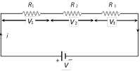 (ii) \[{{R}_{eq}}={{R}_{1}}+{{R}_{2}}+{{R}_{3}}\] equivalent resistance is greater than the maximum value of resistance in the combination.
(iii) If n identical resistance are connected in series \[{{R}_{eq}}=nR\] and potential difference across each resistance \[V'=\frac{V}{n}\]
(2) Parallel grouping
(i) Same potential difference appeared across each resistance but current distributes in the reverse ratio of their resistance i.e. \[i\propto \frac{1}{R}\]
(ii) \[{{R}_{eq}}={{R}_{1}}+{{R}_{2}}+{{R}_{3}}\] equivalent resistance is greater than the maximum value of resistance in the combination.
(iii) If n identical resistance are connected in series \[{{R}_{eq}}=nR\] and potential difference across each resistance \[V'=\frac{V}{n}\]
(2) Parallel grouping
(i) Same potential difference appeared across each resistance but current distributes in the reverse ratio of their resistance i.e. \[i\propto \frac{1}{R}\]
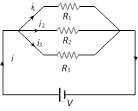 (ii) Equivalent resistance is given by \[\frac{1}{{{R}_{eq}}}=\frac{1}{{{R}_{1}}}+\frac{1}{{{R}_{2}}}+\frac{1}{{{R}_{3}}}\] or \[{{R}_{eq}}={{(R_{1}^{-1}+R_{2}^{-1}+R_{3}^{-1})}^{-1}}\] or \[{{R}_{eq}}=\frac{{{R}_{1}}{{R}_{2}}{{R}_{3}}}{{{R}_{1}}{{R}_{2}}+{{R}_{2}}{{R}_{3}}+{{R}_{2}}{{R}_{1}}}\]
Equivalent resistance is smaller than the minimum value of resistance in the combination.
(iv) If two resistance in parallel
\[{{R}_{eq}}=\frac{{{R}_{1}}{{R}_{2}}}{{{R}_{1}}+{{R}_{2}}}=\frac{\text{Multiplication}}{\text{Addition}}\]
(v) Current through any resistance
\[i\,'=i\times \left[ \frac{\text{Resistance of opposite branch}}{\text{Total resistance }} \right]\]
Where \[i'=\] required current (branch current), \[i=\]main current
(ii) Equivalent resistance is given by \[\frac{1}{{{R}_{eq}}}=\frac{1}{{{R}_{1}}}+\frac{1}{{{R}_{2}}}+\frac{1}{{{R}_{3}}}\] or \[{{R}_{eq}}={{(R_{1}^{-1}+R_{2}^{-1}+R_{3}^{-1})}^{-1}}\] or \[{{R}_{eq}}=\frac{{{R}_{1}}{{R}_{2}}{{R}_{3}}}{{{R}_{1}}{{R}_{2}}+{{R}_{2}}{{R}_{3}}+{{R}_{2}}{{R}_{1}}}\]
Equivalent resistance is smaller than the minimum value of resistance in the combination.
(iv) If two resistance in parallel
\[{{R}_{eq}}=\frac{{{R}_{1}}{{R}_{2}}}{{{R}_{1}}+{{R}_{2}}}=\frac{\text{Multiplication}}{\text{Addition}}\]
(v) Current through any resistance
\[i\,'=i\times \left[ \frac{\text{Resistance of opposite branch}}{\text{Total resistance }} \right]\]
Where \[i'=\] required current (branch current), \[i=\]main current
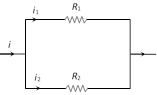 \[{{i}_{1}}=i\,\left( \frac{{{R}_{2}}}{{{R}_{1}}+{{R}_{2}}} \right)\]
and \[{{i}_{2}}=i\,\left( \frac{{{R}_{1}}}{{{R}_{1}}+{{R}_{2}}} \right)\]
(vi) In n identical resistance are connected in parallel \[{{R}_{eq}}=\frac{R}{n}\] and current through each resistance \[i'=\frac{i}{n}\]
\[{{i}_{1}}=i\,\left( \frac{{{R}_{2}}}{{{R}_{1}}+{{R}_{2}}} \right)\]
and \[{{i}_{2}}=i\,\left( \frac{{{R}_{1}}}{{{R}_{1}}+{{R}_{2}}} \right)\]
(vi) In n identical resistance are connected in parallel \[{{R}_{eq}}=\frac{R}{n}\] and current through each resistance \[i'=\frac{i}{n}\] 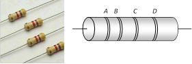 Colour band A and B : Indicate the first two significant figures of resistance in ohm.
B and C : Indicates the decimal multiplier i.e. the number of zeros that follows the two significant figures A and B.
B and D : Indicates the tolerance in percent about the indicated value or in other words it represents the percentage accuracy of the indicated value.
The tolerance in the case of gold is \[\pm 5%\] and in silver is \[\pm 10%\]. If only three bands are marked on carbon resistance, then it indicate a tolerance of 20%.
Colour code for carbon resistance
Colour band A and B : Indicate the first two significant figures of resistance in ohm.
B and C : Indicates the decimal multiplier i.e. the number of zeros that follows the two significant figures A and B.
B and D : Indicates the tolerance in percent about the indicated value or in other words it represents the percentage accuracy of the indicated value.
The tolerance in the case of gold is \[\pm 5%\] and in silver is \[\pm 10%\]. If only three bands are marked on carbon resistance, then it indicate a tolerance of 20%.
Colour code for carbon resistance
| Letters as an aid to memory | Colour | Figure (A, B) | Multiplier (C) |
| B | Black | 0 | \[{{10}^{o}}\] |
| B | Brown | 1 | \[{{10}^{1}}\] |
| more...
(1) Filament of electric bulb : Is made up of tungsten which has high resistivity, high melting point.
(2) Element of heating devices (such as heater, geyser or press) : Is made up of nichrome which has high resistivity and high melting point.
(3) Resistances of resistance boxes (standard resistances) : Are made up of alloys (manganin, constantan or nichrome) these materials have moderate resistivity which is practically independent of temperature so that the specified value of resistance does not alter with minor changes in temperature.
(4) Fuse-wire : Is made up of tin-lead alloy (63% tin + 37% lead). It should have low melting point and high resistivity. It is used in series as a safety device in an electric circuit and is designed so as to melt and thereby open the circuit if the current exceeds a predetermined value due to some fault. The function of a fuse is independent of its length. Safe current of fuse wire relates with it's radius as \[i\propto {{r}^{\mathbf{3/2}}}\].
(5) Thermistors : A thermistor is a heat sensitive resistor usually prepared from oxides of various metals such as nickel, copper, cobalt, iron etc. These compounds are also semi-conductor. For thermistors \[\alpha \] is very high which may be positive or negative. The resistance of thermistors changes very rapidly with change of temperature.
 Thermistors are used to detect small temperature change and to measure very low temperature.
If a conducting wire stretches, it's length increases, area of cross-section decreases so resistance increases but volume remain constant.
Suppose for a conducting wire before stretching it's length \[={{l}_{1}},\] area of cross-section \[={{A}_{1}},\] radius \[={{r}_{1}},\] diameter \[={{d}_{1}},\] and resistance \[{{R}_{1}}=\rho \frac{{{l}_{1}}}{{{A}_{1}}}\]
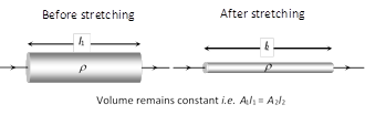 After stretching length \[={{l}_{2}},\] area of cross-section \[={{A}_{2}},\] radius \[={{r}_{2}},\] diameter \[={{d}_{2}}\] and resistance \[={{R}_{2}}=\rho \frac{{{l}_{2}}}{{{A}_{2}}}\]
Ratio of resistances before and after stretching
\[\frac{{{R}_{\mathbf{1}}}}{{{R}_{\mathbf{2}}}}=\frac{{{l}_{\mathbf{1}}}}{{{l}_{\mathbf{2}}}}\times \frac{{{A}_{\mathbf{2}}}}{{{A}_{\mathbf{1}}}}={{\left( \frac{{{l}_{\mathbf{1}}}}{{{l}_{\mathbf{2}}}} \right)}^{\mathbf{2}}}={{\left( \frac{{{A}_{\mathbf{2}}}}{{{A}_{\mathbf{1}}}} \right)}^{\mathbf{2}}}={{\left( \frac{{{r}_{\mathbf{2}}}}{{{r}_{\mathbf{1}}}} \right)}^{\mathbf{4}}}={{\left( \frac{{{d}_{\mathbf{2}}}}{{{d}_{\mathbf{1}}}} \right)}^{\mathbf{4}}}\]
(1) If length is given then \[R\propto {{l}^{2}}\,\Rightarrow \,\frac{{{R}_{1}}}{{{R}_{2}}}={{\left( \frac{{{l}_{1}}}{{{l}_{2}}} \right)}^{2}}\]
(2) If radius is given then \[R\propto \frac{1}{{{r}^{4}}}\,\Rightarrow \,\frac{{{R}_{1}}}{{{R}_{2}}}={{\left( \frac{{{r}_{2}}}{{{r}_{1}}} \right)}^{4}}\]
After stretching length \[={{l}_{2}},\] area of cross-section \[={{A}_{2}},\] radius \[={{r}_{2}},\] diameter \[={{d}_{2}}\] and resistance \[={{R}_{2}}=\rho \frac{{{l}_{2}}}{{{A}_{2}}}\]
Ratio of resistances before and after stretching
\[\frac{{{R}_{\mathbf{1}}}}{{{R}_{\mathbf{2}}}}=\frac{{{l}_{\mathbf{1}}}}{{{l}_{\mathbf{2}}}}\times \frac{{{A}_{\mathbf{2}}}}{{{A}_{\mathbf{1}}}}={{\left( \frac{{{l}_{\mathbf{1}}}}{{{l}_{\mathbf{2}}}} \right)}^{\mathbf{2}}}={{\left( \frac{{{A}_{\mathbf{2}}}}{{{A}_{\mathbf{1}}}} \right)}^{\mathbf{2}}}={{\left( \frac{{{r}_{\mathbf{2}}}}{{{r}_{\mathbf{1}}}} \right)}^{\mathbf{4}}}={{\left( \frac{{{d}_{\mathbf{2}}}}{{{d}_{\mathbf{1}}}} \right)}^{\mathbf{4}}}\]
(1) If length is given then \[R\propto {{l}^{2}}\,\Rightarrow \,\frac{{{R}_{1}}}{{{R}_{2}}}={{\left( \frac{{{l}_{1}}}{{{l}_{2}}} \right)}^{2}}\]
(2) If radius is given then \[R\propto \frac{1}{{{r}^{4}}}\,\Rightarrow \,\frac{{{R}_{1}}}{{{R}_{2}}}={{\left( \frac{{{r}_{2}}}{{{r}_{1}}} \right)}^{4}}\] Current Affairs CategoriesArchive
Trending Current Affairs






You need to login to perform this action. |