Power System
Category : Railways
Power System
BASIC POWER GENERATIONS CONCEPT
Energy exists in various forms like mechanical energy, electrical energy, thermal energy and so on. One form of energy can be converted into another form by suitable arrangements. Out of these forms, electrical energy is preferred due to the following reasons.
In all power stations, electric energy is generated from other forms of energy e.g.
Accordingly power stations are classified as:
(A) Thermal Power Stations
Those power stations which convert chemical energy of fuel (coal, diesel etc.) into electrical energy are called thermal power stations. The fuel used in thermal power stations maybe solid fuel (coal) or liquid fuel (diesel).
The chemical energy of fuel is used to run the prime mover to which is coupled the alternator (A.C. generator). Thus electrical energy is obtained from the alternator.
According to the prime-mover employed for driving the alternate, thermal power stations may be broadly divided into the following two important types:
(a) Steam power stations: Steam power stations employing steam engine or turbine as the prime-mover. Coal is used fuel.
(b) Diesel power stations: Diesel power stations employing diesel engine as the prime-mover.

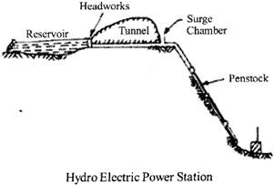
(B) Hydro-electric Power Stations
These convert energy of falling water (hydraulic) into Electrical energy The entire arrangements can be divided into the following stages for the sake of simplicity:
(C) Nuclear Power Stations
These convert nuclear energy into electrical energy.
Nuclear power reactor:
Nuclear power reactor is basically that part of nuclear power plant where energy released as a result of nuclear fission of radioactive material is utilized to heat the coolant which may in turn generate steam or be used in a gas turbine. The nuclear reactor may thus be regarded as a substitute for the boiler fire box of steam plant or combustion chamber or a gas turbine plane. The steam or the gas may be used as working fluid in nuclear power plant. The nuclear power plant maybe of steam driven turbine or gas driven turbine as per the choice of the fluid.

The following Junctions are associated with the working of nuclear reactor:
(i) Producing a chain reacting or critical system,
(ii) Controlling the level of power release from the system,
(iii) Using spare neutrons to convert fertile into fissile material,
(iv)Protecting personnel from harmful radiations emanating from the core.
TRANSMISSION
At the generating station bulk electrical power is generated by 3 phase synchronous generator operating in parallel. The usual generating voltage is 11kv. It may be 6.6kv or even 33kv in certain areas. In order to reduce line losses the generated voltage is stepped up upto 430kv and the power is transmitted with the help of 3phase transformers at the generating station itself. The transmission system can be divided into two sub systems.
Primary transmission:
High voltages of the order of 66 kV 132 kV 220 kV and 400 kV are used for transmitting power by 3 phase 3 wire overhead system. This is supplied to substations usually at the out skirts of major distribution center or city.
Secondary transmission: The primary voltage is reduced to low values of the order of 3.3 kV, 11 kV or 33 kV for secondary transmission.
INSULATOR
Types of Insulators
(a) Pin type insulator:
(b) Suspension type insulator:
(c) Strain insulator:
(d) Shackle insulators:
(e) Stay insulators:
DISTRIBUTION SYSTEM
It is a system through which power is distributed to various consumers for utilization.
The entire power distribution system can be divided into two sub systems
Primary distribution: The transmission line or inner connectors terminate at large main substations from which the power is distributed to small secondary substations scattered throughout the load area. The voltage may range from 11 kV to 132 kV.
Secondary distribution: This consists of the low-voltage network laid along the streets, localities and over the rural areas. From these sources connections to individual customers are provided-
The circuit used for this purpose is 3 phase 4 wire, 440 V/220 V from which either 3 phase 440 V or single phase 220 V supply to the consumers may be provided.
It is part of power system which distributes electric power for local use
(i) Radial feeder system:
(ii) Parallel feeder system:
(iii) Interconnected network system:
PERUNTT QUANTITIES IN POWER SYSTEMS
The per unit system is a method of expression quantities in an electrical system (e.g. voltage, current, impedance etc.) as a proportion of pre-defined base quantities. By defination, The ratio of actual quantity to the base quantity is said to be par unit quantity.
\[Per\,\,unit\,\,quantity\,{{Q}_{pu}}=\frac{quantit{{y}_{actual}}}{qunantit{{y}_{base}}}\]
\[{{Q}_{pu}}\]is the per unit quantity dimension less or just "pu".
For example, suppose the base value of current is 100 A, then a current of 50 A has a per unit value of 50/100 = 0.5 pu
Per unit Voltage \[{{V}_{pu}}=\frac{quantit{{y}_{actual}}}{quantit{{y}_{base}}}\]
\[{{I}_{pu}}=\frac{I\,\,(Amps)}{{{I}_{base}}(amps)}=\frac{{{I}_{(amps)}}}{\frac{{{I}_{base}}}{{{V}_{base}}}}\]
Where, \[{{S}_{base}}={{V}_{base}}={{I}_{base}}\]
\[{{Z}_{pu}}=\frac{Z\,\,(ohm)}{{{Z}_{base}}(ohm)}=Z\,\,(ohm)+\frac{{{I}_{base}}}{{{V}_{base}}}\]
\[=\frac{Z\,\,(ohm).{{S}_{base}}}{{{V}^{2}}_{base}}\]
FAULTANALYSIS
(i) Single line to ground fault: Under this condition,
\[{{V}_{a}}=0,\,\,{{I}_{b}}=0\,\,and\,\,{{I}_{c}}=0\]
A solidly grounded, unloaded alternator: \[L-G\]fault on phase a. Interconnection of sequence networks for \[L-G\]fault
Fault current: \[{{I}_{a}}=\frac{3{{E}_{a}}}{{{Z}_{1}}+{{Z}_{2}}+{{Z}_{0}}}\]

(ii) Line to line fault: Under this condition,
\[{{V}_{b}}={{V}_{c}},{{I}_{a}}=0\,\,and\,\,{{I}_{b}}={{I}_{c}}\]

L-L fault on an unloaded and neutral grounded alternator
(iii) Double line to ground fault: Under this condition,
\[{{I}_{a}}=0,\,\,{{V}_{b}}=0\,\,and\,\,{{V}_{c}}=0\]
A solidify grounded, unloaded alternator, \[L-L-G\]fault
Fault current \[={{I}_{a1}}=\frac{{{E}_{a}}}{{{Z}_{1}}+\frac{{{Z}_{0}}{{Z}_{2}}}{{{Z}_{2}}+{{Z}_{0}}}}\]

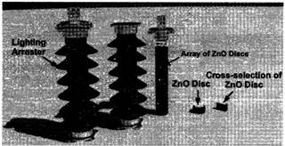
LIGHTNING ARRESTER OR SURGE ARRESTER
A lightning arrester is a device used on electrical power systems and telecommunications systems to protect the insulation and conductors of the system from the damaging effects of lightning. The typical lightning arrester has a high-voltage terminal and a ground terminal. When a lightning surge (or switching surge, which is very similar) travels along the power line to the arrester, the current from the surge is diverted through the arrester, in most cases to earth.
An electrical surge can be occurred in an electrical power transmission system due to various reasons. Surge in electrical system originated mainly due to lightning impulses and switching impulses. Electrical surge produces a large transient over voltage in the electrical network and system. The shape of the transient over voltage has a steeply rising front with slowly decaying tail as shown-in the figure below. This steep voltage wave travels through the electrical network and causes over voltage stresses on all the electrical insulators and equipment come under its travelling path.

That is why all electrical equipment and insulators of power system must be protected against electrical surges. The method of protecting system from surge is normally referred as surge protection.
To protect (all electrial) equipment from surges, lightning arrester is must. In electrical sub-station, arresters are mainly used at the entrance of any feeders and also they are used at both rides of electrical power transformers as transformer is also considered as inductive load and very costly equipment. In modem era, gap less ZnO or zinc oxide surge arresters are mainly used for surge protection.
ELECTRICAL CONDUCTING MATERIAL
Electrical conducting materials are the basic requirement for electrical engineering products. The electrical conducting material can be classified as below-
Based on Resistivity or Conductivity
A classification chart of conducting materials based on resistivity or conductivity is shown in figure below-

Low Resistivity or High Conductivity Conducting Material
Materials having low resistivity or high conductivity are very useful in electrical engineering products. These material used as conductors for all kind of windings required in electrical machines, apparatus and devices. These materials are also used as conductor in transmission and distribution of electrical energy.
Some of low resistivity or high conductivity materials and their resistivity are given in table below -
High Resistivity or Low Conductivity Conducting Material
Materials having High resistivity or Low conductivity conducting are very useful for electrical engineering products. These material are used to manufacture the filaments for incandescent lamp, heating elements for electric heaters, space heaters and electric irons etc. Some of materials having High resistivity or Low conductivity are listed below:
A classification chart of conducting materials based on their applications is shown in figure below-
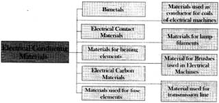
Based on Area of Application are:
ELECTRICAL POWER CABLE
Electric power can be transmitted or distributed either by overhead system or by underground cable. Cables are mainly designed as per requirement. Power cables are mainly used for power transmission and distribution purpose. It is an assembly of one or more individually insulated electrical conductors. used for transmission and distribution of electrical power.
Electrical power cables maybe installed as permanent wiring within buildings, buried in the ground and run overhead or exposed. Flexible power cables are used for portable devices. mobile tools and machinery. These are designed and manufactured as per voltage, current to be carried, operating maximum temperature and purpose of applications desired by customer. For mining, we give extra mechanical strength to cable with double armouring. For wind power plant customers generally require flexible and UV protected cable with mechanical tough sheath so we design as per their requirement. The underground cables have several advantages such as less liable to damage through storms, lightning, low maintenance cost, less chances of faults, smaller voltage drop and better general appearance.
Construction of Power Cable
"There are various parts of a cable to be taken care of during construction. The power cable mainly consists of

EARTHING
Equipment earthing is a connection done through a metal link between the body of any electrical appliance, or neutral point to the deeper ground soil. The metal link is normally of MS flat, G flat, GI wire which should be penetrated to the ground earth grid.
Necessity of Equipment Earthing Protection
Classification of Earthing
The earthing is broadly classified into two type:
It is a earthing between earth & (Connection between part of plant in an operating devices like LV neutral of a power transformer winding)
It is a earthing between earth or safety grounding & (connecting bodies of equipment like electric motor body, transformer tank, switchgear box, operating rods of air break switches, LV breaker body, HV breaker body, feeder breaker bodies etc).
Permissible Values of Earth Resistance
Earth Resistances: earth resistance is the ratio of touch voltage and maximum current in fault conditions.
\[\text{resistance=}\frac{\text{Touch}\,\,\text{voltage}}{{{\text{I}}_{\text{fault}}}}\text{=}\frac{{{\text{V}}_{\text{touch}}}}{{{\text{I}}_{\text{fault}}}}\]
Where:
\[{{I}_{fault}}=\]Maximum current in fault conditions
\[{{V}_{touch}}\]\[=\]Touch Voltage.
ELECTRICAL CIRCUIT BREAKER
Electrical circuit breaker is a switching device which can be operated manually and automatically for controlling and protection of electrical power system respectively. As the modem power system deals with huge currents, the special attention should be given during designing of circuit breaker for safe interruption of arc produced during the operation of circuit breaker. This was the basic definition of circuit breaker.
Types of Circuit Breaker
According different criteria there are different types of circuit breaker. According to their arc quenching media the circuit breaker can be divided as-
According to their arc quenching media the circuit breaker can be divided as-
According to their services the circuit breaker can be divided as-
According to the operating mechanism of circuit breaker they can be divided as-
According to the voltage level of installation types of circuit breaker are referred as-


You need to login to perform this action.
You will be redirected in
3 sec

