Engineering Mechanics and Strength of Materials
Category : Railways
Engineering Mechanics and Strength of Materials
ENGINEERING MECHANICS
It is the branch of Engineering Science which deals with the principles of mechanics along with their applications to the field problems.
Engineering Mechanics can be divided into its sub-groups as below
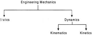
Statics deals with forces in terms of their distribution and effect on a body at absolute or relative rest. Dynamics deals with the study of bodies in motion. Dynamics is further divided into kinematics and kinetics. Kinematics is concerned with the bodies in motion without taking into account the forces which are responsible for the motion. kinematics deals with the bodies in motion and its causes.
Force System: A force system may be coplanar/non-coplanar. in a coplanar force system, all the forces act in the same plane. In a non-coplanar force system, all the forces act in different planar.
Classification of force system: (For coplanar forces)
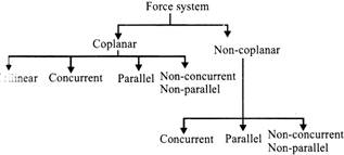
(Complete classification of force system)
Law of parallelogram:
According to law of parallelogram, if two forces are acting at a point and may be showed in magnitude and direction by two adjacent sides of the parallelogram, then the resultant of the two forces will be shown by the diagonal of the parallelogram in megnitude and direction. Let 'F and 'Q' are two forces acting at the point '0' Here 'P' and '6' shows the sides of the parallelogram and 'R' is the resultant.
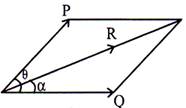
Let \[\theta \]=Angle between the two forces 'P' and 'Q'
\[\alpha \]= Angle between resultant 'R' and one of the force
('Q' in this case)
= direction of the resultant then,
Then,
Resultant' \['R'=\sqrt{{{P}^{2}}+{{Q}^{2}}+2PQ\cos \theta }\]
Angle made by resultant \['R'=\left( \frac{P\sin \theta }{Q+P\cos \theta } \right)\]
or,
\[\tan \,\,\alpha =\left( \frac{P\sin \theta }{Q+P\cos \theta } \right)\Rightarrow \alpha ={{\tan }^{-1}}\left( \frac{P\sin \theta }{Q+P\cos \theta } \right)\]Land's theorem:
According to Lam is theorem, if three forces are acting at a point and the forces are in equilibrium, then the each of the three forces is directly proportional to the sine of the angle between the other two forces.
Let, P, Q, R = Three forces in equilibrium
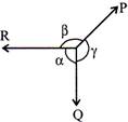
\[\alpha \],\[\beta \], \[\gamma \]= Angles included between three forces P, Q and R then,
\[\frac{P}{\sin \alpha }=\frac{Q}{\sin \beta }=\frac{R}{\sin \gamma }\]
Moment of a force: It is defined or the product of the magnitude of the force and the perpendicular distance of the point from the line of action of the force.
Moment (M) \[=F\times ~r\]
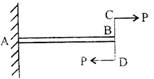
Couple: Two parallel forces equal in magnitude and opposite in direction and separated by a definite distance are Said to form a couple.
Action and Reaction: From Newton's third law, for every action there is a equal and opposite reaction.
Friction: Friction may be denned as the resistive force acting at the surface of contact between two bodies that resist motion of one body relative to another.
Based on the nature of two surfaces in contact, friction in categorised in the following two kinds/types.
(a) Static friction When two contact surfaces are at rest, then the force experienced by one surface is termed or static friction.
(b) Dynamic friction: When one of the two contact bodies starts moving and the other in at rest, the force experienced by the body in motion is called dynamic friction.
Co-efficient of friction\[(\mu )\]: It is defined as the ratio of limiting force of friction (F) to the normal reaction (R) between two rigid bodies.
\[\mu =\frac{F}{R}\Rightarrow F=\mu R\]
Angle of friction\[(\phi )\]: It is defined as the angle subtended by the resultant of normal reaction with the limiting force of friction with the normal reaction.
Angle of repose\[(\alpha )\]: When a body rests on an inclined plane, the angle by which the body is at the verge (just) to start moving in terms as angle of repose.
Cone of friction: It is defined as the right circular cone with vertex at point of contact of two surfaces and axis in the direction of normal reactions.
Methods of reducing friction:
There are many ways to reduce friction some of them are given as follows:
LAW OF CONSERVATION OF LINEAR MOMENTUM
Through experimental observations it has been found that if no external force acts on a system (called isolated) of constant mass (called closed) the total momentum of the system remains constant (with time).
If the total external force acting on a system is equal to zero, then the final value of the total momentum of the system is equal to the initial value of the total momentum of the system.
\[{{\overrightarrow{F}}_{ext}}=\frac{d\overrightarrow{p}}{dt}\]
If \[\overrightarrow{F}=0,\] \[i.e.,\frac{d\overrightarrow{p}}{dt}=0\] then
\[\overrightarrow{P}=cons\tan t\] or \[\overrightarrow{P}f={{\overrightarrow{P}}_{i}}\]
The law may be extended to a system of particles or to the centre of mass of a system of particles.
Free Body Diagram (FBD)
A free body diagram is a diagram showing the chosen body by itself, “free” of its surroundings, with vectors drawn to show magnitude and directions of all the forces applied to the body the various other bodies that interact with it.
Contact Force
Contact force arises when one body is in physical contact with another.
Ex.: Force exerted by ropes or springs, the force involve in collisions, the force of friction between two surfaces, and force exerted by a fluid on its container.
Two bodies in contact
Two blocks of masses \[{{m}_{1}}\]and\[{{m}_{2}}\]placed in contact with other on a frictioniess horizontal surface.
If a force F be applied on block of mass\[{{m}_{1}}\].
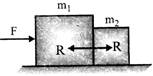
Acceleration of both the blocks,
\[a=\frac{F}{{{m}_{1}}+{{m}_{2}}}\]
Let the force of contact = R
By FBD of\[{{m}_{1}}\]
\[F-R={{m}_{1}}a\]
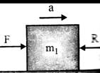
\[FBD\,\,of\,\,{{m}_{1}}\]
\[R=F-{{m}_{1}}a=F-{{m}_{1}}\,\,\left( \frac{F}{{{m}_{1}}+{{m}_{2}}} \right)\]
\[=\left( 1-\frac{{{m}_{1}}}{{{m}_{1}}+{{m}_{2}}} \right)=\frac{{{m}_{2}}F}{{{m}_{1}}+{{m}_{2}}}\]
If force F is applied on block of mass\[{{m}_{2}}\]
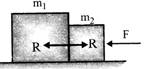
Common acceleration, \[a=\frac{F}{{{m}_{1}}+{{m}_{2}}}\]
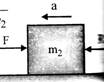
By FBD of \[{{m}_{2}}\]
\[F-{{R}_{1}}={{m}_{2}}a\]
or \[{{R}_{1}}=F-{{m}_{2}}a\]
or \[{{R}_{1}}=F-{{m}_{2}}\,\,\left[ \frac{F}{{{m}_{1}}+{{m}_{2}}} \right]\]
\[=\left[ 1-\frac{{{m}_{1}}}{{{m}_{1}}+{{m}_{2}}} \right]\,\,F=\frac{{{m}_{1}}F}{{{m}_{1}}+{{m}_{2}}}\]
NEWTON'S LAWS OF MOTION
There are three laws of motion known as Newton's laws of motion.
Momentum=\[m\overrightarrow{v}\]
\[\therefore \] \[\frac{d\,\,(m\overrightarrow{v})}{dt}=\overrightarrow{F}\]
![]()
Where m = mass of the body
\[\overrightarrow{v}\]= velocity of the body
\[\overrightarrow{F}\]= Force acting on the body
\[\overrightarrow{a}\]= acceleration produced in the body.
GRAVITATIONAL LAW
Gravitational law is also known as universal law of gravitation. According to this law, Every substance or body has an attractive force with another substance or body and this attractive force is directly proportional to the product of their masses and inversely proportional to the square of distance between their centers.
This attrative force is directed along the line which joins the centers of bodies.
Lei \[{{M}_{1}}\]and\[{{M}_{2}}\]be the masses of two bodies and 'R' be the distance between the centers of two bodies. 'F' be the attractive force or force of attraction between those bodies.
Now, According to law,
\[F\propto {{M}_{1}}\times {{M}_{2}}\]
and \[F\propto \frac{1}{{{R}^{2}}}\]
On combining the above two expressions,
\[F\propto \frac{{{M}_{1}}{{M}_{2}}}{{{R}^{2}}}\]
\[F=G\frac{{{M}_{1}}{{M}_{2}}}{{{R}^{2}}}\]
Where, G = universal gravitational constant
\[=6.67\times {{10}^{-11}}N{{M}^{2}}/k{{g}^{2}}\]
ANGULAR DISPLACEMENT
The displacement of a body in rotation is called angular displacement. Angular displacement is a vector quantity. Angular displacement\[\theta \]can be measured in radians, degrees or revolutions.
\[\text{1}\,\,\text{revolution=2 }\!\!\pi\!\!\text{ }\,\text{radians=360}\,\,\text{degrees}\]
ANGULAR VELOCITY
The rate of change of angular displacement of a body with respect to time is called angular velocity.
\[\omega \text{=}\frac{d\theta }{dt}\]
if a body is rotating at N r. p. m. then corresponding angular velocity
\[\omega \text{=}\frac{2\pi N}{60}\,\,rad/s\]
If the body is rotating o) rad/'s along a circular path of radius r, then its linear velocity \[(v)\]is given by
\[v=\omega r\]
ANGULAR ACCELERATION
The rate of change of angular velocity is called angular acceleration. It is expressed in \[rad/{{s}^{2}}\]
\[\propto =\frac{d\omega }{dt}\]
Centripetal and centrifugal force
Essential force for a circular motion acting radially inwards is called centripetal force which is given by
\[{{F}_{C}}=m\,\,{{w}^{2}}r\]b
where m is the mass of the body
w = angular velocity
r = radius of the circular path
As per Newton's third law of motion, the body must exert a force radially outwards of equal.
BEHAVIOR OF MATERIAL PARTICLES
The behavior of material systems is controlled by universal physical laws. Perhaps the most ubiquitous of these are the law of mass conservation, the laws of motion invented by Newton's in 1687.
A material particle contains four types of law:
Law for material volume:
A material volume contains the same particles of matter at all times.
A particular material volume may be defined by the closed bounding surface that envelops its material particles at a certain time. Since every point of a material volume's bounding surface moves (by definition) with the local material velocity y (Fig- below), the shape of the volume at all other times is determined by the laws of dynamics.
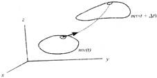
Fig. A material volume moves with the material particles it encloses.
Laws for material particles:
The simplest forms of the four basic laws apply to an infinitesimal material particle that is so small that the velocity v, density p, thermodynamic temperature, and other intrinsic properties are essentially uniform within it. An observer moving with a particle ("sitting on it," as it was) would see its properties change with time only (Fig. below)
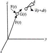
Fig. Motion of a material particle between time t and time \[t+\Delta t\]
For a material particle with infinitesimal volume\[\delta V(t)\], density\[\rho (t)\], and velocity\[\overrightarrow{v}\], the three laws have the following familiar forms:
Mass conservation
\[\frac{d}{dt}(\rho \delta V)=0\] (1)
This law asserts that the mass \[dM=\rho \delta V\]of a material particle remains invariant. (The prefix p indicates quantities that are of infinitesimal size, and the prefix d refers to changes that occur in the indicated property in time dt.)
Newton's law of(non-relativistic) linear motion
\[(\rho \delta V)\frac{d\overrightarrow{v}}{dt}=\delta \overrightarrow{F,}\]\[or\,\,\frac{d}{dt}(\rho \overrightarrow{v}\delta V)=\delta \overrightarrow{F}\] (2)
Newton's law states that, relative to an inertial reference frame, the product of a particle's mass and acceleration is at every instant equal to the net force \[\delta \vec{F}\,\,\left( t \right)\]exerted on it by the rest of the universe, or alternatively, that the rate of change of a particle's momentum (a vector quantity) is equal at every instant to the force applied to the particle by the rest of the universe. (Actually the law states that the rate of change of momentum is proportional to the applied force, with the coefficient being universal, but in most systems of measurement the universal coefficient is set equal to unity, which determines the units of force in terms of those of acceleration and time.)
Newton's law appliet to angular motion
\[\frac{d}{dt}\,\,(\overrightarrow{r}\times \rho \overrightarrow{v}\delta V)=\overrightarrow{r}\times \delta \overrightarrow{F}\] (3)
This law figures in rotary motion. The rate of change of a particle's angular momentum (the quantity in brackets on the left side of
(3), \[\overrightarrow{r}\,\,(t)\]being the particle's positon vector) is at every instant equal to the net torque exerted on the particle by the rest of the universe. This is not a new law, but one that follows from Eq. (2). Equation (3) is obtained by taking the cross product of\[\overrightarrow{r}\](t) Eq. (2), using Eq. (1), and noting that \[\overleftarrow{dr}|dt\times \overrightarrow{v}=\overrightarrow{v}\times \overrightarrow{v}=0\] Like the law is is derived from, Eq. (3) is valid only in inertical reference frames. Actually the law states that the rate of change of momentum is proportional to the applied force, with the coefficient being universal, but in most systems of measurement the universal coefficient is set equal to unity, which determines the units of force in terms of those of acceleration and time.
STRENGTH OF MATERIALS
Load: It is defined as external force or couple to which a component is subjected during its functionality.
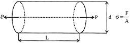
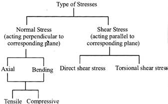
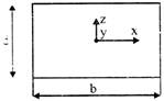
Stress: It is defined as the intensity of internal resisting force M developed at a point against the deformation cuased due to the load acting at the member.
Stress developed in one direction\[\to \]uniaxial state of stress
Stress developed in two direction\[\to \]biaxial state of stress
Stress developed in three direction\[\to \]triaxial state of stress
Units of Stress
\[SI\,\,:\,\,Pa,\,\,MPa,\,\,GPa\] \[1\,\,Pa=1\,\,N/{{m}^{2}}\] \[\frac{1Kgf}{c{{m}^{2}}}=0.1\,\,MPa\]
\[MKS\,\,:\,\,kgf/c{{m}^{2}}\] \[1\,\,MPa={{10}^{6}}\,\,N/{{m}^{2}}\]
\[1\,\,GPa={{10}^{9}}\,\,N/{{m}^{2}}\]
NOTE
Elongation of a bar subjected to axial load P
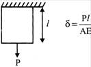
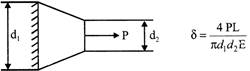
Elongation of a tapered bar subjected to axial load P
Elongation of a prismatic bar under its self-weight\[=\frac{\gamma {{L}^{2}}}{2E}\]
\[\gamma =\] self-weight per unit volume

Elongation of a conical bar under its self-weight \[=\frac{\gamma {{L}^{2}}}{6E}\]
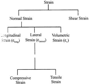
STRAIN
Strain is defined as the ratio of change in dimension to original dimension.
SHEAR STRESS
It is defined as the change in initial right angle between two line elements which are parallel to x and y axes respectively.
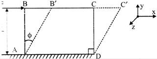
Shear strain = Shear angle \[\left( \phi \right)\]
Relationship Between Elastic Constants
\[E=2G(1+\mu )\]
\[E=3K(1-2\mu )\]
\[E=\frac{9KG}{3K+G}\]
\[G=\frac{E}{2}\times \frac{1}{1-2\mu }\]
\[K=\frac{E}{3}\times \frac{1}{1-2\mu }\]
Value of any \[EC\ge 0\]
Note: \[{{\mu }_{cork}}=0\]
Young's Modulus or Modulus of Elasticity
As per Hooke's law upto proportional limit normal stress is directly propotional to longitudinal strain
\[\sigma \propto {{\varepsilon }_{long}}\]
\[\sigma =E=\text{young }\!\!'\!\!\text{ s}\,\,\text{modulu}{{\text{s}}_{long}}\]
\[E\uparrow \Rightarrow {{\varepsilon }_{long}}\downarrow \Rightarrow \delta l\downarrow \]
\[\therefore \] A material having higher E value is chosen
\[{{E}_{MS}}=200GPa\]
\[{{E}_{A1}}=\frac{200}{3}GPa\]
\[\therefore {{(\delta l)}_{MS}}<{{(\delta l)}_{CI}}<{{(\delta )}_{Al}}\]
Elastic Limit: Maximum value of stress upto which a material can be completely elastic.
PROPERTIES OF MATERIALS
(a) Elasticity: It is the property of the material due to which it regains its original shape after the external load is removed after applied. Perfectly elastic bodies are those bodies which returns to their original shape completely.
(b) Plasticity: It is the property of the material due to which it does not regain its original shape after the removed of external load. Plasticity is the opposite of elasticity of external load. Plasticity is the opposite of elasticity.
(c) Ductility: It is the property of the material due to which if can be drawn into thin wires. The length of deformation is very large in a ductile material.
(d) Brittleness: material is said to be brittle if the length of deformation is very little in tension. A brittle material haslack of ductility. A brittle material tails at a very small deformation.
(e) Malleability: It is the property of the material due to which it can be converted into thin sheets in compression. This property is used in forging, rolling etc.
(f) Toughness: It is the property of the material due to which a maximum amount of energy stored in a material upto fractors. This property is utilized under the action of shock or impact loading.
(g) Hardness: It is the property of the material due to which it resists cutting, scractehing, pinetration or in dilation.
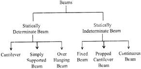
Types of plans:
Various types of beams are given as follows:
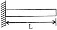
(a) Cantiliver beam: A cantiliver beam has one of its end is fixed and the other end is free.
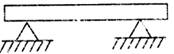
(b) Simply supported beam: A simply supported beam has both of its ends are supported.
![]()
(c) Overhanging beam: In overhanging beam, the supports are not placed at the end of the beam and also one or both ends are entended over the supports.
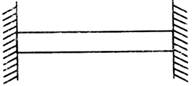
(d) Fixed beam: In fixed beam, both of its ends are rigidly fixed into the supporting walls.
(e) Continuous beams: In continuous beams, there are more than two supports.
![]()
Bending Stress
As BM= const
\[\therefore \] above beam is under pure bending.
Bending Equation
![]()
\[{{M}_{R}}\]: moment of resistance offered by plane of cross-section of beam.
\[({{\sigma }_{b}})\]: bending stress at a distance 'y' from Neutral Axis.
R : Radius of curvature.
E : Young's modulus.
\[{{I}_{NA}}\]:area moment of inertia of plane of cross-section abol
Neutral Axis.
Shear Stresses in Beams
\[\tau =\frac{PA\,\,\overline{y}}{{{I}_{NA}}.b}\]
P : shear force on plane of cross-section.
A : area.
\[\overline{y}\]: distance of hatched portion from neutral axis.
\[{{I}_{NA}}\]: moment of inertia of entire cross-section about neutral axis.
b : width.
DEFLECTION OF BEAMS
Deflection of beams plays an important role in design beams for rigidity criterion.
The expressions of deflections are further used determination of natural frequencies of shaft under transverse vibrations.
For a cantilever beam under any loading condition deflection is maximum at free end.
In simply supported beam, deflection is maximum mid-span (when beam is subjected to symmetric load- only).


You need to login to perform this action.
You will be redirected in
3 sec

