Logic Gates
Category : JEE Main & Advanced
(i) AND : It is the boolean function defined by
\[f({{x}_{1}},{{x}_{2}})={{x}_{1}}\wedge {{x}_{2}}\]; \[{{x}_{1}},\,{{x}_{2}}\in \{0,\,1\}\].
It is shown in the figure given below.
![]()
| Input | Output | |
| \[{{x}_{1}}\] | \[{{x}_{2}}\] | \[{{x}_{1}}\wedge {{x}_{2}}\] |
| 1 1 0 0 | 1 0 1 0 | 1 0 0 0 |
(ii) OR : It is the boolean function defined by
\[f({{x}_{1}},{{x}_{2}})={{x}_{1}}\vee {{x}_{2}}\]; \[{{x}_{1}},{{x}_{2}}\in \{0,\,1\}\].
It is shown in the figure given below
![]()
| Input | Output | |
| \[{{x}_{1}}\] | \[{{x}_{2}}\] | \[{{x}_{1}}\vee {{x}_{2}}\] |
| 1 1 0 0 | 1 0 1 0 | 1 1 1 0 |
(iii) NOT : It is the boolean function defined by
\[f(x)={x}',\] \[x\in \{0.1\}\]
It is shown in the figure given below:
![]()
| Input | Output |
| x 1 0 | x¢ 0 1 |
Combinational circuit :
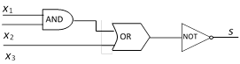
In the above figure, output s in uniquely defined for each combination of inputs \[{{x}_{1}},{{x}_{2}}\] and \[{{x}_{3}}\]. Such a circuit is called a combinatorial circuit or combinational circuit.
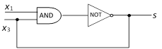
In the above figure, if \[{{x}_{1}}=1,{{x}_{2}}=0\], then the inputs to the AND gate are 1 and 0 and so the output of the AND gate is ‘0’ (Minimum of 1 and 0). This is the input of NOT gate which gives the output \[s=1\].
But the diagram states that \[{{x}_{2}}=s\] i.e. \[0=1\], a contradiction.
\[\therefore \]The output s is not uniquely defined. This type of circuit is not a combinatorial circuit.
Two combinatorial circuits : Circuit having inputs \[{{x}_{1}},{{x}_{2}},......{{x}_{n}}\] and a single output are said to be combinatorial circuit if, the circuits receive the same input, they produce the same output i.e., if the input/output tables are identical.


You need to login to perform this action.
You will be redirected in
3 sec

