More About Logic Gates
Category : 10th Class
More About Logic Gates
Introduction
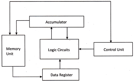
The internal architecture of computer performs operations like, mathematical as well as logical operations. Logical and arithmetic operations in the microprocessor of a computer is done by comparing the inputs in which output is depend on the state of input. Combination of logic circuit can be used for addition, logical functions, etc. Combination of logic gates is used to make half adder, full adder in the form of flip flop which is used for the manufacturing of microprocessor. The logic gate is made of logic circuits perform the Boolean function. A basic logic gate obtains one or two input but it produces one output at a time. Logic gates is made of transistors and other devices which supports the function of the transistor, such as, resister. All types of logic circuits are divided into two groups, Basic logic gates and Derived logic gates. The following picture illustrates the application of logic circuits in the microprocessor.
Basic Logic Gates
Basic logic gates are logic circuits which are made of a single logic gate. It is made of transistor and capacitors. The output of the basic logic gate is depend on the switching of transistor.
AND Gate
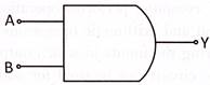
AND gate has two input and one output. The output of the AND gate is also written as, Y = A.B. Output of the AND gate is obtained by multiplying both the input. The input of the AND gate is given as logic high and logic low or 0 and 1. Every logic gate has a truth table which is the statement of input given to the logic gate and output obtained by that logic gate.
Look at the following symbol of the AND gate:
Look at the following truth table of the AND gate:
|
Input |
Output |
|
|
A |
B |
Y = A.B |
|
0 |
0 |
0 |
|
0 |
1 |
0 |
|
1 |
0 |
0 |
|
1 |
1 |
1 |
From the truth table of AND gate, the output is low or 0 if any one of input A or B is low or high and also output is low if both input are low. In the case of both input high, the output of the AND gate is high.
OR Gate
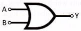
The OR gate also has two input and one output. The output equation of a OR gate is written as, Y = A + B. Hence, output of the OR gate is obtained by adding both binary input.
Look at the following symbol of the OR gate:
Look at the following truth of the OR gate:
|
Input |
Output |
|
|
A |
B |
Y=A+B |
|
0 |
0 |
0 |
|
0 |
1 |
1 |
|
1 |
0 |
1 |
|
1 |
1 |
1 |
From the truth table of the OR Gate, the output is low if both input are low and output is high if any one input is high or both input are high.
NOT Gate
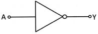
NOT gate has one input and one output. The output of the NOT gate is obtained inverted input. If input of the NOT gate is low the output will be high and vice versa. Hence, the output equation of a NOT gate, Y = where A is the input.
Look at the following symbol of the NOT Gate:
Look at the following truth table of the NOT Gate:
|
Input |
Output |
|
A |
Y= |
|
0 |
1 |
|
1 |
0 |
From the above truth table of the NOT Gate, the output is the inverted input. The output is high if input is low and output is low if input is high.
Derived Logic Gates
Derived logic gate is defined as the combination of basic logic gates. A derived logic gate has two inputs and one output. The input of a derived logic gate may be more than two if it is made by the combination of many logic gates.
NAND Gate
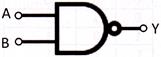
NAND gate is the combination of both AND and NOT gate. A not gate in the form of bubble is connected at the output of the AND gate which inverts the output produced by the AND gate. A NAND gate has two input and one output. The output equation fora NAND gate, Y == ![]() Hence, from the output equation of a NAND gate, we can say that the output of a NAND gate is the inverted product of its both input.
Hence, from the output equation of a NAND gate, we can say that the output of a NAND gate is the inverted product of its both input.
Look at the following symbol of the NAND Gate:
Look at the following truth table of the NAND Gate:
|
Input |
Output |
|
|
A |
B |
Y= |
|
0 |
0 |
1 |
|
0 |
1 |
1 |
|
1 |
0 |
1 |
|
1 |
1 |
0 |
From the truth table of a NAND gate, when both input are logic low, the output will be high and low output produced by it when both input are logic high. The output of the NAND gate is high even if one of the input is logic low as shown in the truth table above.
NOR Gate
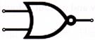
NOR gate is the combination of both OR and NOT gate. A NOT gate in the form of -bubble is connected at the output of a OR gate which produces the inverted output produced by the OR gate. A NOR gate has two input and one output. The output equation of a NOR gate, Y = ![]() Hence, from the output equation of a NOR gate, we can say that the output of a NOR gate is the inverted sum of its both input.
Hence, from the output equation of a NOR gate, we can say that the output of a NOR gate is the inverted sum of its both input.
Look at the following symbol of the NOR Gate:
Look at the following truth table of the NOR Gate:
|
Input |
Output |
|
|
A |
B |
Y= |
|
0 |
0 |
1 |
|
0 |
1 |
1 |
|
1 |
0 |
1 |
|
1 |
1 |
0 |
Form the truth table of the NOR gate, the output of the NOR gate is high when both input of the gate is logic low. The NOR gate produces logic low output when one of the input is logic low and another is logic high or both inputs are logic high as shown in the truth table above.
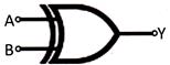
XOR Gate
XOR gate is also called exclusive OR gate can be used for one binary bit adder and also used for many applications in digital circuits. A XOR gate is made using many NAND gate, NOR gate and also it can be made from the combination of many basic logic gates. The output equation of a XOR gate = Y =A.![]() +
+ ![]() B. Hence, output of a XOR gate is depend on both the input.
B. Hence, output of a XOR gate is depend on both the input.
Look at the following symbol of the XOR Gate:
Look at the following truth table of XOR Gate:
|
Input |
Output |
|
|
A |
B |
|
|
0 |
0 |
0 |
|
0 |
1 |
1 |
|
1 |
0 |
1 |
|
1 |
1 |
0 |
In the truth table above, when we put each set of both input in the output equation,
Y= A. ![]() +
+![]() B
B
Y= 0. ![]() +
+![]() . 0 = 0.1 + 1.0 = 0 + 0 = 0 (whereas, A = 0 and B =0)
. 0 = 0.1 + 1.0 = 0 + 0 = 0 (whereas, A = 0 and B =0)
Y= 0. ![]() +
+![]() . 0 = 0.1 + 1.0 = 0 + 0 = 0 (whereas, A = 0 and B = 1)
. 0 = 0.1 + 1.0 = 0 + 0 = 0 (whereas, A = 0 and B = 1)
Y= 0. ![]() +
+![]() . 0 = 0.1 + 1.0 = 0 + 0 = 0 (whereas, A = 1 and B = 0)
. 0 = 0.1 + 1.0 = 0 + 0 = 0 (whereas, A = 1 and B = 0)
Y= 0. ![]() +
+![]() . 0 = 0.1 + 1.0 = 0 + 0 = 0 (whereas, A = 1 and B = 1)
. 0 = 0.1 + 1.0 = 0 + 0 = 0 (whereas, A = 1 and B = 1)
From the truth table of the XOR Gate, the output is high if the inputs are unequal whereas output is low if both inputs are equal.
Application of Logic Gates
Microprocessor of a computer contains logic circuits for performing the operations, such as, addition and comparison.
Look at the following picture of a full adder made of the combination of many logic gates in the picture below:
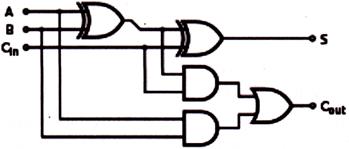
In the picture above, A and B are the input and Cin, Cout, are the carry in and carry out respectively. S is the sum. Output.
In the picture above, two XOR gate, two AND gate and one OR gate have been used to construct a logic circuit for one bit full adder. The combination of many full adder circuits can be used to construct the circuit of more than one bit full adder which are fabricated on the silicon chip of the microprocessor to work for the input data.


You need to login to perform this action.
You will be redirected in
3 sec

