 For good demodulation of AM signal of carrier frequency f, the value of RC should be:
A) \[RC=\frac{1}{f}\]
B) \[RC<\frac{1}{f}\]
C) \[RC\ge \frac{1}{f}\]
D) \[RC>>\frac{1}{f}\]
Correct Answer: D
Solution :
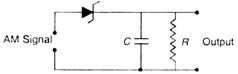
From the modulated signal, we can demodulate or detect the modulating or message signal by using a diode and a suitable capacitor filter. The AM signal given to the input of the circuit appears at the output of the diode as a rectified wave as shown. For good demodulation of AM signal the value of RC (which is a time-constant) is chosen such that \[\frac{1}{f}<<RC\] or \[RC>>\frac{1}{f}\] where f is the frequency of the carrier signal.


You need to login to perform this action.
You will be redirected in
3 sec

