-
question_answer1)
| Direction: Q.1 to Q.5 |
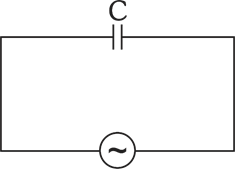
| Let a source of alternating e.m.f. \[E={{E}_{0}}\sin \omega t\] be connected to a capacitor of capacitance C. If I' is the instantaneous value of current in the circuit as instant t, then \[I=\frac{{{E}_{0}}}{1/\omega C}\sin \left( \omega t+\frac{\pi }{2} \right)\]. The capacitive reactance limits the amplitude of current in a purely capacitive circuit and it is given by \[{{X}_{C}}=\frac{1}{\omega C}\]. |
 |
| Read the above passage carefully and give the answer of the following questions: |
What is the unit of capacitive reactance?
A)
farad done
clear
B)
ampere done
clear
C)
ohm done
clear
D)
\[oh{{m}^{-1}}\] done
clear
View Solution play_arrow
-
question_answer2)
The capacitive reactance of a \[5\text{ }\mu F\]capacitor for a frequency of \[{{10}^{6}}\] Hz is:
A)
\[0.032\text{ }\Omega \] done
clear
B)
\[2.52\text{ }\Omega \] done
clear
C)
\[1.25\text{ }\Omega \] done
clear
D)
\[4.51\text{ }\Omega \] done
clear
View Solution play_arrow
-
question_answer3)
In a capacitive circuit, resistance to the flow of current is offered by:
A)
resistor done
clear
B)
capacitor done
clear
C)
inductor done
clear
D)
frequency done
clear
View Solution play_arrow
-
question_answer4)
In a capacitive circuit, by what value of phase angle does alternating current leads the e.m.f.?
A)
\[45{}^\circ \] done
clear
B)
\[90{}^\circ \] done
clear
C)
\[75{}^\circ \] done
clear
D)
\[60{}^\circ \] done
clear
View Solution play_arrow
-
question_answer5)
One microfarad capacitor is joined to a 200V, 50Hz alternator. The rms current through capacitor is:
A)
\[6.28\times {{10}^{-2}}A\] done
clear
B)
\[7.5\times {{10}^{-4}}A\] done
clear
C)
\[10.52\times {{10}^{-2}}A\] done
clear
D)
\[15.25\times {{10}^{-2}}A\] done
clear
View Solution play_arrow
-
question_answer6)
| Direction: Q.6 to Q.10 |
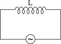
| Let a source of alternating e.m.f. \[E={{E}_{0}}\sin \,\,\omega t\] be connected to a circuit containing a pure inductance L. If l is the value of instantaneous current in the circuit, then \[l={{l}_{0}}\sin \left( \omega t-\frac{\pi }{2} \right)\]. The inductive reactance limits the current in a purely inductive circuit and is given by \[{{X}_{L}}=\omega L\]. |
 |
| Read the above passage carefully and give the answer of the following questions: |
A 100 hertz AC is flowing in 14 mH coil. The reactance is:
A)
\[15\,\Omega \] done
clear
B)
\[7.5\,\Omega \] done
clear
C)
\[8.8\,\Omega \] done
clear
D)
\[10\,\Omega \] done
clear
View Solution play_arrow
-
question_answer7)
In a pure inductive circuit, resistance to the flow of current is offered by:
A)
resistor done
clear
B)
inductor done
clear
C)
capacitor done
clear
D)
resistor and inductor done
clear
View Solution play_arrow
-
question_answer8)
In a inductive circuit, by what value of phase angle does alternating current lags behind e.m.f.?
A)
\[45{}^\circ \] done
clear
B)
\[90{}^\circ \] done
clear
C)
\[120{}^\circ \] done
clear
D)
\[75{}^\circ \] done
clear
View Solution play_arrow
-
question_answer9)
How much inductance should be connected to 200 V, 50 Hz AC supply so that a maximum current of 0.9 A flows through it?
A)
5 H done
clear
B)
1 H done
clear
C)
10 H done
clear
D)
4.5 H done
clear
View Solution play_arrow
-
question_answer10)
The maximum value of current when inductance of 2 H is connected to 150V, 50 Hz supply is:
A)
0.337 A done
clear
B)
0.721 A done
clear
C)
1.521 A done
clear
D)
2.522 A done
clear
View Solution play_arrow
-
question_answer11)
| Direction: Q.11 to Q.15 |
| The power averaged over one full cycle of AC is known as average power. It is also known as true power. \[{{P}_{av}}={{V}_{rms}}{{I}_{rms}}\cos \phi =\frac{{{V}_{0}}{{I}_{0}}}{2}\cos \phi \]. |
| Root mean square or simply rms watts refer to continuous power. |
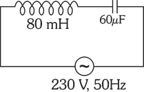
| A circuit containing a 80 mH inductor and a \[60\text{ }\mu F\] capacitors in series is connected to a 230 V, 50 Hz supply. The resistance of the circuit is negligible. |
 |
| Read the above passage carefully and give the answer of the following questions: |
The value of current amplitude is:
A)
15 A done
clear
B)
11.63 A done
clear
C)
17.65 A done
clear
D)
6.33 A done
clear
View Solution play_arrow
-
question_answer12)
Find rms value.
A)
6 A done
clear
B)
5.25 A done
clear
C)
8.23 A done
clear
D)
7.52 A done
clear
View Solution play_arrow
-
question_answer13)
The average power transferred to inductor is:
A)
zero done
clear
B)
7 W done
clear
C)
2.5 W done
clear
D)
5W done
clear
View Solution play_arrow
-
question_answer14)
The average power transferred to the capacitor is:
A)
5 W done
clear
B)
zero done
clear
C)
11 W done
clear
D)
15 W done
clear
View Solution play_arrow
-
question_answer15)
What is the total average power absorbed by the circuit?
A)
zero done
clear
B)
10 W done
clear
C)
2.5 W done
clear
D)
15 W done
clear
View Solution play_arrow
-
question_answer16)
| Direction: Q.16 to Q.20 |
| An LC circuit also called a resonant circuit, tank circuit or tuned circuit is an electric circuit consisting of an inductor represented by the letter L and a capacitor, represented by the letter C connected together. An LC circuit is an idealised model since it assumes there is no dissipation of energy due to resistance. |
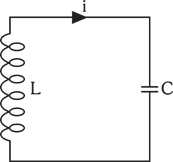 |
| An LC circuit contains a 20 mH inductor and a \[50\,\mu F\] capacitor with an initial charge of 10 mC. The resistance of the circuit is negligible. Let the instant the circuit is closed be t = 0. |
| Based on the above information, answer the following questions. . |
The total energy stored initially is:
A)
5 J done
clear
B)
3 J done
clear
C)
10 J done
clear
D)
1 J done
clear
View Solution play_arrow
-
question_answer17)
The natural frequency of the circuit is:
A)
159.24 Hz done
clear
B)
200.12 Hz done
clear
C)
110.25 Hz done
clear
D)
95 Hz done
clear
View Solution play_arrow
-
question_answer18)
At what time is the energy stored completely electrical?
A)
\[T,5T,9T\] done
clear
B)
\[\frac{T}{2},\frac{5T}{2},\frac{9T}{2}\] done
clear
C)
\[0,T,2T,3T\] done
clear
D)
\[0,\frac{T}{2},T,\frac{3T}{2}\] done
clear
View Solution play_arrow
-
question_answer19)
At what time is the energy stored completely magnetic?
A)
\[\frac{T}{2},\frac{3T}{2},\frac{T}{4}\] done
clear
B)
\[\frac{T}{3},\frac{T}{9},\frac{T}{12}\] done
clear
C)
\[0,2T,3T\] done
clear
D)
\[\frac{T}{4},\frac{3T}{4},\frac{5T}{4}\] done
clear
View Solution play_arrow
-
question_answer20)
The value of \[{{X}_{L}}\] is:
A)
\[20\,\Omega \] done
clear
B)
\[40\,\Omega \] done
clear
C)
\[60\,\Omega \] done
clear
D)
\[50\,\Omega \] done
clear
View Solution play_arrow
-
question_answer21)
| Direction: Q.21 to Q.25 |
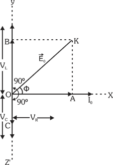
| When a pure resistance R, pure inductor L and an ideal capacitor of capacitance C is connected in series to a source of alternating e.m.f., then current at any instant through the three elements has the same amplitude and is represented as \[I={{I}_{0}}\sin \,\omega t\]. However, voltage across each element has a different phase relationship with the current as shown in graph. |
| The effective resistance of RLC circuit is called impedance (Z) of the circuit and the voltage leads the current by a phase angle \[\phi \]. |
 |
| A resistor of \[12\text{ }\Omega \], a capacitor of reactance \[14\text{ }\Omega \] and a pure inductor of inductance 0.1 H are joined in series and placed across 200 V, 50 Hz AC supply. |
| Based on the above information, answer the following questions. |
The value of inductive reactance is:
A)
\[15\,\Omega \] done
clear
B)
\[31.4\,\Omega \] done
clear
C)
\[20\,\Omega \] done
clear
D)
\[30\,\Omega \] done
clear
View Solution play_arrow
-
question_answer22)
The value of impedance is:
A)
\[20\text{ }\Omega \] done
clear
B)
\[\text{15 }\Omega \] done
clear
C)
\[\text{30 }\Omega \] done
clear
D)
\[\text{21}\text{.13 }\Omega \] done
clear
View Solution play_arrow
-
question_answer23)
What is the value of current in the circuit?
A)
5 A done
clear
B)
15 A done
clear
C)
10 A done
clear
D)
9.46 A done
clear
View Solution play_arrow
-
question_answer24)
What is the value of the phase angle between current and voltage?
A)
\[53{}^\circ 9'\] done
clear
B)
\[63{}^\circ 9'\] done
clear
C)
\[55{}^\circ 4'\] done
clear
D)
\[50{}^\circ \] done
clear
View Solution play_arrow
-
question_answer25)
From graph, which one is true from following?
A)
\[{{V}_{L}}\ge {{V}_{C}}\] done
clear
B)
\[{{V}_{L}}<{{V}_{C}}\] done
clear
C)
\[{{V}_{L}}>{{V}_{C}}\] done
clear
D)
\[{{V}_{L}}={{V}_{C}}\] done
clear
View Solution play_arrow
-
question_answer26)
| Direction: Q.26 to Q.30 |
| When the frequency of AC supply is such that the inductive reactance and capacitive reactance become equal, the impedance of the series LCR circuit is equal to the ohmic resistance in the circuit. Such a series LCR circuit is known as resonant series LCR circuit and the frequency of the AC supply is known as resonant frequency. |
| Resonance phenomenon is exhibited by a circuit only if both L and C are present in the circuit. We cannot have resonance in a RL or RC circuit. |
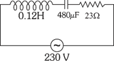 |
| A series LCR circuit with \[L=0.12\text{ }H,\text{ }C=480\text{ }nF,\text{ }R=23\,\Omega \]is connected to a 230 V variable frequency supply. |
| Based on the above information, answer the following questions. |
Find the value of source frequency for which current amplitude is maximum.
A)
222.32 Hz done
clear
B)
550.52 Hz done
clear
C)
663.48 Hz done
clear
D)
770 Hz done
clear
View Solution play_arrow
-
question_answer27)
The value of maximum current is:
A)
14.14 A done
clear
B)
22.52 A done
clear
C)
50.25 A done
clear
D)
47.41 A done
clear
View Solution play_arrow
-
question_answer28)
The value of maximum power is:
A)
2200 W done
clear
B)
2299.3 W done
clear
C)
5500 W done
clear
D)
4700 W done
clear
View Solution play_arrow
-
question_answer29)
What is the Q-factor of the given circuit?
A)
25 done
clear
B)
42.21 done
clear
C)
35.42 done
clear
D)
21.74 done
clear
View Solution play_arrow
-
question_answer30)
At resonance which of the following physical quantity is maximum?
A)
Impedance done
clear
B)
Current done
clear
C)
Both a. and b. done
clear
D)
Neither a, nor b. done
clear
View Solution play_arrow
-
question_answer31)
| Direction: Q.31 to Q.35 |
| Step-down transformers are used to decrease or step-down voltages. These are used when voltages need to be lowered for use in homes and factories. |
| A small town with a demand of 800 kW of electric power at 220 V is situated 15 km away from an electric plant generating power at 440 V. The resistance of the two wire line carrying power is \[0.5\text{ }\Omega \] per km. The town gets power from the line through a 4000-220 V step-down transformer at a sub-station in the town. |
 |
| Based on the above information, answer the following questions. |
The value of total resistance of the wire is:
A)
\[25\,\Omega \] done
clear
B)
\[30\,\Omega \] done
clear
C)
\[35\,\Omega \] done
clear
D)
\[15\,\Omega \] done
clear
View Solution play_arrow
-
question_answer32)
The Line power loss in the form of heat is:
A)
550 kW done
clear
B)
650 kW done
clear
C)
600 kW done
clear
D)
700 kW done
clear
View Solution play_arrow
-
question_answer33)
How much power must the plant supply, assuming there is negligible power loss due to leakage?
A)
600 kW done
clear
B)
1600 kW done
clear
C)
500 W done
clear
D)
1400 kW done
clear
View Solution play_arrow
-
question_answer34)
The voltage drop in the power line is:
A)
1700 V done
clear
B)
3000 V done
clear
C)
2000 V done
clear
D)
2800 V done
clear
View Solution play_arrow
-
question_answer35)
The total value of voltage transmitted from the plant is:
A)
500 V done
clear
B)
4000 V done
clear
C)
3000 V done
clear
D)
7000 V done
clear
View Solution play_arrow
-
question_answer36)
| Direction: Q.36 to Q.40 |
| In an AC circuit, values of voltage and current change every instant. Therefore, power of an AC circuit at any instant is the product of instantaneous voltage (E) and instantaneous current (I). The average power supplied to a pure resistance R over a complete cycle as AC is \[P={{E}_{v}}{{I}_{v}}\]. When circuit is inductive, average power per cycle is \[{{E}_{v}}{{I}_{v}}\,\cos \phi \]. |
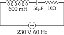 |
| In an AC circuit, 600 mH inductor and a \[50\,\mu F\]capacitor are connected in series with \[10\,\Omega \] resistance. The AC supply to the circuit is 230 V, 60 Hz. |
| Based on the above information, answer the following questions. |
The average power transferred per cycle to resistance is:
A)
10.42 W done
clear
B)
15.25 W done
clear
C)
17.42 W done
clear
D)
13.45 W done
clear
View Solution play_arrow
-
question_answer37)
The average power transferred per cycle to capacitor is:
A)
zero done
clear
B)
10.42 W done
clear
C)
17.42 W done
clear
D)
15 W done
clear
View Solution play_arrow
-
question_answer38)
The average power transferred per cycle to inductor is:
A)
25 W done
clear
B)
17.42 W done
clear
C)
16.52 W done
clear
D)
zero done
clear
View Solution play_arrow
-
question_answer39)
The total power transferred per cycle by all the three circuit elements is:
A)
17.42 W done
clear
B)
10.45 W done
clear
C)
12.45 W done
clear
D)
zero done
clear
View Solution play_arrow
-
question_answer40)
The electrical energy spend in running the circuit for one hour is:
A)
\[7.5\times {{10}^{5}}J\] done
clear
B)
\[10\times {{10}^{3}}J\] done
clear
C)
\[9.4\times {{10}^{3}}J\] done
clear
D)
\[6.2\times {{10}^{4}}J\] done
clear
View Solution play_arrow
-
question_answer41)
| Direction: Q.41 to Q.45 |
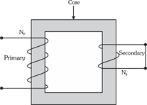
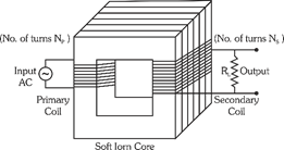
| A transformer is an electrical device which is used for changing the AC voltages. It is based on the phenomenon of mutual induction i.e., whenever the amount of magnetic flux linked with a coil changes, an e.m.f. is induced in the neighbouring coil. For an ideal transformer, the resistances of the primary and secondary windings are negligible. |
 |
| It can be shown that \[\frac{{{E}_{S}}}{{{E}_{P}}}=\frac{{{I}_{P}}}{{{I}_{S}}}=\frac{{{n}_{S}}}{{{n}_{P}}}=k\] |
| where the symbols have their standard meanings. |
| For a step up transformer, |
| \[{{n}_{S}}>{{n}_{P}};{{E}_{S}}>{{E}_{P}};k>1;\] |
| \[\therefore {{I}_{S}}<{{I}_{P}}\] |
| For a step down transformer, |
| \[{{n}_{S}}<{{n}_{P}};{{E}_{S}}<{{E}_{P}};k<1\] |
| The above relations are on the assumptions that efficiency of transformer is 100%. |
| Infact, efficiency \[\eta =\frac{\text{output}\,\,\text{power}}{\text{input}\,\,\text{power}}=\frac{{{E}_{S}}{{I}_{S}}}{{{E}_{P}}{{I}_{P}}}\] |
| Based on the above information, answer the following questions. |
Which of the following quantity remains constant in an ideal transformer?
A)
Current done
clear
B)
Voltage done
clear
C)
Power done
clear
D)
All of these done
clear
View Solution play_arrow
-
question_answer42)
Transformer is used to:
A)
convert AC to DC voltage done
clear
B)
convert DC to AC voltage done
clear
C)
obtain desired DC power done
clear
D)
obtain desired AC voltage and current done
clear
View Solution play_arrow
-
question_answer43)
The number of turns in primary coil of a transformer is 20 and the number of turns in a secondary is 10. If the voltage across the primary is 220 AC V, what is the voltage across the secondary?
A)
100 AC V done
clear
B)
120 AC V done
clear
C)
110 AC V done
clear
D)
220 AC V done
clear
View Solution play_arrow
-
question_answer44)
In a transformer the number of primary turns is four times that of the secondary turns. Its primary is connected to an AC source of voltage V. Then:
A)
current through its secondary is about four times that of the current through its primary done
clear
B)
voltage across its secondary is about four times that of the voltage across its primary done
clear
C)
voltage across its secondary is about two times that of the voltage across its primary done
clear
D)
voltage across its secondary is about \[\frac{1}{2\sqrt{2}}\] times that of the voltage across its primary done
clear
View Solution play_arrow
-
question_answer45)
A transformer is used to light 100 W-110 V lamp from 220V mains. If the main current is 0.5 A, the efficiency of the transformer is:
A)
95% done
clear
B)
99% done
clear
C)
90% done
clear
D)
96% done
clear
View Solution play_arrow
-
question_answer46)
| Direction: Q.46 to Q.50 |
| A transformer is essentially an AC device. It cannot work on DC. It changes alternating voltages or currents. It does not affect the frequency of AC. It is based on the phenomenon of mutual induction. A transformer essentially consists of two coils of insulated copper wire having different number of turns and wound on the same soft iron core. |
| The number of turns in the primary and secondary coils of an ideal transformer are 2000 and 50 respectively. The primary coil is connected to a main supply of 120 V and secondary coil is connected to a bulb of resistance \[0.6\text{ }\Omega \]. |
| Based on the above information, answer the following questions. |
The value of voltage across the secondary coil is:
A)
5 V done
clear
B)
2 V done
clear
C)
3 V done
clear
D)
10 V done
clear
View Solution play_arrow
-
question_answer47)
The value of current in the bulb is:
A)
7 A done
clear
B)
15 A done
clear
C)
3 A done
clear
D)
5 A done
clear
View Solution play_arrow
-
question_answer48)
The value of current in primary coil is:
A)
0.125 A done
clear
B)
2.52 A done
clear
C)
1.51 A done
clear
D)
3.52 A done
clear
View Solution play_arrow
-
question_answer49)
Power in primary coil is:
A)
20 W done
clear
B)
5 W done
clear
C)
10 W done
clear
D)
15 W done
clear
View Solution play_arrow
-
question_answer50)
Power in secondary coil is:
A)
15 W done
clear
B)
20 W done
clear
C)
7 W done
clear
D)
8 W done
clear
View Solution play_arrow