 The logic circuit gate is:
A) OR gate
B) AND gate
C) NAND gate
D) NOR gate
Correct Answer: B
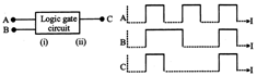
Solution :
From the given input and output waveforms, the truth table can be constructed as given| A | B | C |
| 0 | 0 | 0 |
| 1 | 1 | 1 |
| 0 | 1 | 0 |
| 1 | 0 | 0 |


You need to login to perform this action.
You will be redirected in
3 sec

