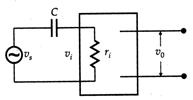
 Which of the following figures give the correct variation of the magnitude of output voltage as a function of the frequency? ( \[{{\upsilon }_{s}}\] does not change with frequency)


Answer:
Figure (a) gives the correct variation of the magnitude of output voltage as a function of frequency. This is because the capacitor offers a reactance \[{{X}_{C}}\], given by \[{{X}_{C}}=\frac{1}{2\pi fC}\] For small values of\[f,{{X}_{C}}\]is high and, therefore \[{{\upsilon }_{i}}=\frac{{{\upsilon }_{s}}}{{{X}_{C}}}\] is low. As \[f\] increases, \[{{X}_{C}}\] decreases. This in turns, increases \[{{\upsilon }_{i}}\] and hence output voltage \[{{\upsilon }_{0}}={{A}_{\upsilon }}.{{\upsilon }_{i}}\] also increases. At a certain value of \[f,{{X}_{C}}\] becomes negligible, \[{{\upsilon }_{i}}\] becomes nearly equal to \[{{\upsilon }_{s}}\] and then \[{{\upsilon }_{0}}\] becomes constant.


You need to login to perform this action.
You will be redirected in
3 sec

