-
question_answer1)
Two identical capacitors are joined in parallel, charged to a potential V and then separated and then connected in series \[i.e.\] the positive plate of one is connected to negative of the other [NCERT 1972, 73, 82; KCET 1993]
A)
The charges on the free plates connected together are destroyed done
clear
B)
The charges on the free plates are enhanced done
clear
C)
The energy stored in the system increases done
clear
D)
The potential difference in the free plates becomes \[2V\] done
clear
View Solution play_arrow
-
question_answer2)
The condensers of capacity \[{{C}_{1}}\]and \[{{C}_{2}}\] are connected in parallel, then the equivalent capacitance is [NCERT 1977; KCET 2000; DPMT 2002; MP PMT 2004]
A)
\[{{C}_{1}}+{{C}_{2}}\] done
clear
B)
\[\frac{{{C}_{1}}{{C}_{2}}}{{{C}_{1}}+{{C}_{2}}}\] done
clear
C)
\[\frac{{{C}_{1}}}{{{C}_{2}}}\] done
clear
D)
\[\frac{{{C}_{2}}}{{{C}_{1}}}\] done
clear
View Solution play_arrow
-
question_answer3)
A parallel plate capacitor is made by stacking \[n\] equally spaced plates connected alternately. If the capacitance between any two plates is \[C\] then the resultant capacitance is [NCERT 1971; DPMT 2001; MP PMT 2003; AIEEE 2005]
A)
\[C\] done
clear
B)
\[nC\] done
clear
C)
\[(n-1)C\] done
clear
D)
\[(n+1)C\] done
clear
View Solution play_arrow
-
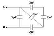
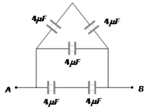
question_answer4)
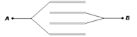
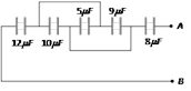
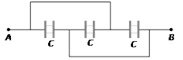
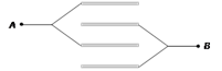
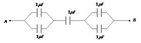
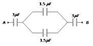
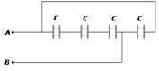
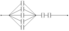
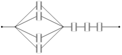
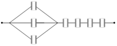
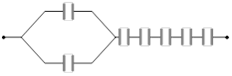
Seven capacitors each of capacity \[2\mu F\] are to be so connected to have a total capacity \[\frac{10}{11}\mu F\]. Which will be the necessary figure as shown [IIT 1990]
A)
B)
C)
D)
View Solution play_arrow
-
question_answer5)
Four plates of equal area \[A\]are separated by equal distances \[d\] and are arranged as shown in the figure. The equivalent capacity is
A)
\[\frac{2{{\varepsilon }_{0}}A}{d}\] done
clear
B)
\[\frac{3{{\varepsilon }_{0}}A}{d}\] done
clear
C)
\[\frac{3{{\varepsilon }_{0}}A}{d}\] done
clear
D)
\[\frac{{{\varepsilon }_{0}}A}{d}\] done
clear
View Solution play_arrow
-
question_answer6)
The capacitor of capacitance \[4\mu F\] and \[6\mu F\] are connected in series. A potential difference of \[500\ volts\] applied to the outer plates of the two capacitor system. Then the charge on each capacitor is numerically
A)
\[6000\,C\] done
clear
B)
\[1200\ C\] done
clear
C)
\[1200\ \mu C\] done
clear
D)
\[6000\ \mu C\] done
clear
View Solution play_arrow
-
question_answer7)
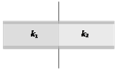
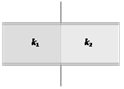
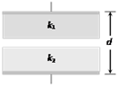
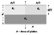
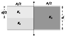
A parallel plate capacitor with air as medium between the plates has a capacitance of \[10\mu F\]. The area of capacitor is divided into two equal halves and filled with two media as shown in the figure having dielectric constant \[{{k}_{1}}=2\]and \[{{k}_{2}}=4\]. The capacitance of the system will now be [MP PMT 1987; RPET 2001]
A)
x\[10\mu F\] done
clear
B)
\[20\mu F\] done
clear
C)
\[30\mu F\] done
clear
D)
\[40\mu F\] done
clear
View Solution play_arrow
-
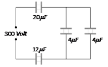
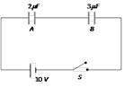
question_answer8)
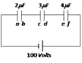
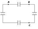
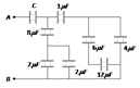
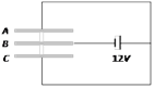
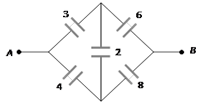
Three capacitors are connected to \[D.C.\] source of \[100\ volts\] shown in the adjoining figure. If the charge accumulated on plates of \[{{C}_{1}},\ {{C}_{2}}\]and \[{{C}_{3}}\] are \[{{q}_{a}},\ {{q}_{b}},\ {{q}_{c}},{{q}_{d}}.{{q}_{e}}\]and\[{{q}_{f}}\] respectively, then [CPMT 1986]
A)
\[{{q}_{b}}+{{q}_{d}}+{{q}_{f}}=\frac{100}{9}\,C\] done
clear
B)
\[{{q}_{b}}+{{q}_{d}}+{{q}_{f}}=0\] done
clear
C)
\[{{q}_{a}}+{{q}_{c}}+{{q}_{e}}=50\,C\] done
clear
D)
\[{{q}_{b}}={{q}_{d}}={{q}_{f}}\] done
clear
View Solution play_arrow
-
question_answer9)
\[n\] identical condensers are joined in parallel and are charged to potential\[V\]. Now they are separated and joined in series. Then the total energy and potential difference of the combination will be [MP PET 1993]
A)
Energy and potential difference remain same done
clear
B)
Energy remains same and potential difference is \[nV\] done
clear
C)
Energy increases \[n\] times and potential difference is \[nV\] done
clear
D)
Energy increases \[n\] times and potential difference remains same done
clear
View Solution play_arrow
-
question_answer10)
Three capacitors each of capacitance \[1\mu F\]are connected in parallel. To this combination, a fourth capacitor of capacitance \[1\mu F\] is connected in series. The resultant capacitance of the system is [MP PMT 1985]
A)
\[4\mu F\] done
clear
B)
\[2\mu F\] done
clear
C)
\[\frac{4}{3}\mu F\] done
clear
D)
\[\frac{3}{4}\mu F\] done
clear
View Solution play_arrow
-
question_answer11)
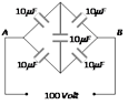
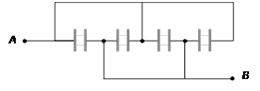
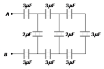
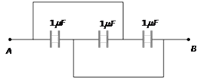
Five capacitors of \[10\mu F\]capacity each are connected to a d.c. potential of \[100\ volts\] as shown in the adjoining figure. The equivalent capacitance between the points \[A\]and\[B\] will be equal to [CPMT 1986, 88; MP PMT 1999]
A)
\[40\mu F\] done
clear
B)
\[20\mu F\] done
clear
C)
\[30\mu F\] done
clear
D)
\[10\mu F\] done
clear
View Solution play_arrow
-
question_answer12)
Three capacitors of capacitances \[3\mu F,\ 9\mu F\] and \[18\mu F\] are connected once in series and another time in parallel. The ratio of equivalent capacitance in the two cases \[\left( \frac{{{C}_{s}}}{{{C}_{p}}} \right)\] will be [CPMT 1990]
A)
1 : 15 done
clear
B)
15 : 1 done
clear
C)
1 : 1 done
clear
D)
1 : 3 done
clear
View Solution play_arrow
-
question_answer13)
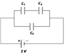
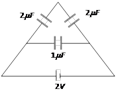
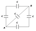
Four condensers each of capacity \[4\mu F\] are connected as shown in figure. \[{{V}_{P}}-{{V}_{Q}}=15\,volts\]. The energy stored in the system is [CPMT 1976, 89]
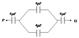
A)
\[2400\ ergs\] done
clear
B)
\[1800\ ergs\] done
clear
C)
\[3600\ ergs\] done
clear
D)
\[5400\ ergs\] done
clear
View Solution play_arrow
-
question_answer14)
Two capacitors each of \[1\mu F\] capacitance are connected in parallel and are then charged by \[200\ volts\] d.c. supply. The total energy of their charges (in joules) is [MP PMT 1990, 2002]
A)
0.01 done
clear
B)
0.02 done
clear
C)
0.04 done
clear
D)
0.06 done
clear
View Solution play_arrow
-
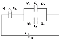
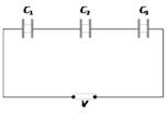
question_answer15)
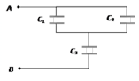
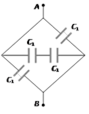
In an adjoining figure are shown three capacitors \[{{C}_{1}}\],\[{{C}_{2}}\] and \[{{C}_{3}}\] joined to a battery. The correct condition will be (Symbols have their usual meanings) [CPMT 1988, 89]
A)
\[{{Q}_{1}}={{Q}_{2}}={{Q}_{3}}\] and \[{{V}_{1}}={{V}_{2}}={{V}_{3}}=V\] done
clear
B)
\[{{Q}_{1}}={{Q}_{2}}+{{Q}_{3}}\]and\[V={{V}_{1}}+{{V}_{2}}+{{V}_{3}}\] done
clear
C)
\[{{Q}_{1}}={{Q}_{2}}+{{Q}_{3}}\] and \[V={{V}_{1}}+{{V}_{2}}\] done
clear
D)
\[{{Q}_{2}}={{Q}_{3}}\] and \[{{V}_{2}}={{V}_{3}}\] done
clear
View Solution play_arrow
-
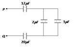
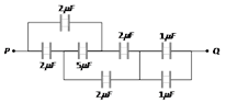
question_answer16)
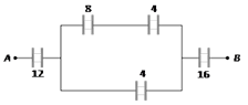
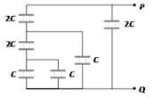
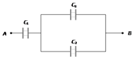
. In the circuit diagram shown in the adjoining figure, the resultant capacitance between P and Q is [MP PET/PMT 1988]
A)
\[47\mu F\] done
clear
B)
\[3\mu F\] done
clear
C)
\[60\mu F\] done
clear
D)
\[10\mu F\] done
clear
View Solution play_arrow
-
question_answer17)
Two condensers of capacity \[0.3\mu F\] and \[0.6\mu F\] respectively are connected in series. The combination is connected across a potential of\[6\,volts\]. The ratio of energies stored by the condensers will be [MP PMT 1990]
A)
\[\frac{1}{2}\] done
clear
B)
2 done
clear
C)
\[\frac{1}{4}\] done
clear
D)
4 done
clear
View Solution play_arrow
-
question_answer18)
The capacitor of capacitance \[4\mu F\] and\[6\mu F\] are connected in series. A potential difference of \[500\ volts\] is applied to the outer plates of the two capacitor system. The potential difference across the plates of capacitor of \[4\mu F\] capacitance is
A)
\[500\ volts\] done
clear
B)
\[300\ volts\] done
clear
C)
\[200\ volts\] done
clear
D)
\[250\ volts\] done
clear
View Solution play_arrow
-
question_answer19)
Two capacitances of capacity \[{{C}_{1}}\]and \[{{C}_{2}}\] are connected in series and potential difference \[V\] is applied across it. Then the potential difference across \[{{C}_{1}}\]will be [MP PMT 1985]
A)
\[V\frac{{{C}_{2}}}{{{C}_{1}}}\] done
clear
B)
\[V\frac{{{C}_{1}}+{{C}_{2}}}{{{C}_{1}}}\] done
clear
C)
\[V\frac{{{C}_{2}}}{{{C}_{1}}+{{C}_{2}}}\] done
clear
D)
\[V\frac{{{C}_{1}}}{{{C}_{1}}+{{C}_{2}}}\] done
clear
View Solution play_arrow
-
question_answer20)
Three capacitances of capacity\[10\mu F,\ 5\mu F\] and \[5\mu F\] are connected in parallel. The total capacity will be [MP PET/PMT 1988]
A)
\[10\mu F\] done
clear
B)
\[5\mu F\] done
clear
C)
\[20\mu F\] done
clear
D)
None of the above done
clear
View Solution play_arrow
-
question_answer21)
Three capacitors of capacity \[{{C}_{1}},\ {{C}_{2}}\ {{C}_{3}}\] are connected in series. Their total capacity will be [MP Board 1977; MP PET/PMT 1988; CPMT 1996]
A)
\[{{C}_{1}}+{{C}_{2}}+{{C}_{3}}\] done
clear
B)
\[1/({{C}_{1}}+{{C}_{2}}+{{C}_{3}})\] done
clear
C)
\[{{(C_{1}^{-1}+C_{2}^{-1}+C_{3}^{-1})}^{-1}}\] done
clear
D)
None of these done
clear
View Solution play_arrow
-
question_answer22)
Two capacitors of equal capacity are first connected in parallel and then in series. The ratio of the total capacities in the two cases will be [MP Board 1988; MH CET 2001]
A)
2 : 1 done
clear
B)
1 : 2 done
clear
C)
4 : 1 done
clear
D)
1 : 4 done
clear
View Solution play_arrow
-
question_answer23)
Two capacitors connected in parallel having the capacities \[{{C}_{1}}\]and \[{{C}_{2}}\] are given \['q'\] charge, which is distributed among them. The ratio of the charge on \[{{C}_{1}}\]and \[{{C}_{2}}\] will be [NCERT 1977; MP PET/PMT 1988]
A)
\[\frac{{{C}_{1}}}{{{C}_{2}}}\] done
clear
B)
\[\frac{{{C}_{2}}}{{{C}_{1}}}\] done
clear
C)
\[{{C}_{1}}{{C}_{2}}\] done
clear
D)
\[\frac{1}{{{C}_{1}}{{C}_{2}}}\] done
clear
View Solution play_arrow
-
question_answer24)
Two capacitors of capacities \[{{C}_{1}}\] and \[{{C}_{2}}\] are charged to voltages \[{{V}_{1}}\] and \[{{V}_{2}}\] respectively. There will be no exchange of energy in connecting them in parallel, if [MP PET 1989]
A)
\[{{C}_{1}}={{C}_{2}}\] done
clear
B)
\[{{C}_{1}}{{V}_{1}}={{C}_{2}}{{V}_{2}}\] done
clear
C)
\[{{V}_{1}}={{V}_{2}}\] done
clear
D)
\[\frac{{{C}_{1}}}{{{V}_{1}}}=\frac{{{C}_{2}}}{{{V}_{2}}}\] done
clear
View Solution play_arrow
-
question_answer25)
If three capacitors each of capacity \[1\mu F\]are connected in such a way that the resultant capacity is\[1.5\mu F\], then [MP PET 1989]
A)
All the three are connected in series done
clear
B)
All the three are connected in parallel done
clear
C)
Two of them are in parallel and connected in series to the third done
clear
D)
Two of them are in series and then connected in parallel to the third done
clear
View Solution play_arrow
-
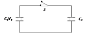
question_answer26)
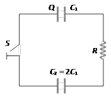
A capacitor of capacity \[{{C}_{1}}\]is charged to the potential of \[{{V}_{o}}\]. On disconnecting with the battery, it is connected with a capacitor of capacity \[{{C}_{2}}\] as shown in the adjoining figure. The ratio of energies before and after the connection of switch \[S\] will be
A)
\[({{C}_{1}}+{{C}_{2}})/{{C}_{1}}\] done
clear
B)
\[{{C}_{1}}/({{C}_{1}}+{{C}_{2}})\] done
clear
C)
\[{{C}_{1}}{{C}_{2}}\] done
clear
D)
\[{{C}_{1}}/{{C}_{2}}\] done
clear
View Solution play_arrow
-
question_answer27)
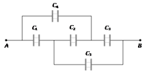
Four capacitors of each of capacity \[3\mu F\]are connected as shown in the adjoining figure. The ratio of equivalent capacitance between \[A\] and \[B\] and between \[A\] and \[C\] will be
A)
4 : 3 done
clear
B)
3 : 4 done
clear
C)
2 : 3 done
clear
D)
3 : 2 done
clear
View Solution play_arrow
-
question_answer28)
The capacities of two conductors are \[{{C}_{1}}\]and \[{{C}_{2}}\] and their respective potentials are \[{{V}_{1}}\]and\[{{V}_{2}}\]. If they are connected by a thin wire, then the loss of energy will be given by [MP PMT 1986]
A)
\[\frac{{{C}_{1}}{{C}_{2}}({{V}_{1}}+{{V}_{2}})}{2({{C}_{1}}+{{C}_{2}})}\] done
clear
B)
\[\frac{{{C}_{1}}{{C}_{2}}({{V}_{1}}-{{V}_{2}})}{2({{C}_{1}}+{{C}_{2}})}\] done
clear
C)
\[\frac{{{C}_{1}}{{C}_{2}}{{({{V}_{1}}-{{V}_{2}})}^{2}}}{2({{C}_{1}}+{{C}_{2}})}\] done
clear
D)
\[\frac{({{C}_{1}}+{{C}_{2}})({{V}_{1}}-{{V}_{2}})}{{{C}_{1}}{{C}_{2}}}\] done
clear
View Solution play_arrow
-
question_answer29)
A parallel plate condenser is filled with two dielectrics as shown. Area of each plate is \[A\ metr{{e}^{2}}\]and the separation is\[t\ metre\]. The dielectric constants are \[{{k}_{1}}\] and \[{{k}_{2}}\] respectively. Its capacitance in farad will be [MNR 1985; DCE 1999; AIIMS 2001]
A)
\[\frac{{{\varepsilon }_{0}}A}{t}({{k}_{1}}+{{k}_{2}})\] done
clear
B)
\[\frac{{{\varepsilon }_{0}}A}{t}.\frac{{{k}_{1}}+{{k}_{2}}}{2}\] done
clear
C)
\[\frac{2{{\varepsilon }_{0}}A}{t}({{k}_{1}}+{{k}_{2}})\] done
clear
D)
\[\frac{{{\varepsilon }_{0}}A}{t}.\frac{{{k}_{1}}-{{k}_{2}}}{2}\] done
clear
View Solution play_arrow
-
question_answer30)
Three condensers each of capacitance \[2F\] are put in series. The resultant capacitance is [CPMT 1976; NCERT 1981; MP PMT 2001]
A)
\[6F\] done
clear
B)
\[\frac{3}{2}F\] done
clear
C)
\[\frac{2}{3}F\] done
clear
D)
\[5F\] done
clear
View Solution play_arrow
-
question_answer31)
Two condensers of capacities \[1\mu F\] and\[2\mu F\] are connected in series and the system is charged to\[120\ volts\]. Then the P.D. on \[1\mu F\] capacitor (in volts) will be [MP PMT 1987]
A)
40 done
clear
B)
60 done
clear
C)
80 done
clear
D)
120 done
clear
View Solution play_arrow
-
question_answer32)
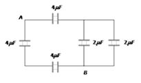
Four condensers are joined as shown in the adjoining figure. The capacity of each is\[8\mu F\]. The equivalent capacity between the points \[A\]and \[B\] will be
A)
\[32\mu F\] done
clear
B)
\[2\mu F\] done
clear
C)
\[8\mu F\] done
clear
D)
\[16\mu F\] done
clear
View Solution play_arrow
-
question_answer33)
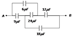
The capacities and connection of five capacitors are shown in the adjoining figure. The potential difference between the points \[A\] and \[B\] is \[60\ volts\]. Then the equivalent capacity between \[A\] and \[B\] and the charge on \[5\mu F\] capacitance will be respectively
A)
\[44\mu F;\ 300\mu C\] done
clear
B)
\[16\mu F;\ 150\mu C\] done
clear
C)
\[15\mu F;\ 200\mu C\] done
clear
D)
\[4\mu F;\ 50\mu C\] done
clear
View Solution play_arrow
-
question_answer34)
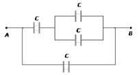
Three equal capacitors, each with capacitance \[C\] are connected as shown in figure. Then the equivalent capacitance between \[A\] and \[B\] is [MP PET 1985, 89]
A)
\[C\] done
clear
B)
\[3C\] done
clear
C)
\[\frac{C}{3}\] done
clear
D)
\[\frac{3C}{2}\] done
clear
View Solution play_arrow
-
question_answer35)
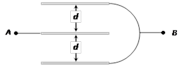
Four plates of the same area of cross-section are joined as shown in the figure. The distance between each plate is\[d\]. The equivalent capacity across A and B will be
A)
\[\frac{2{{\varepsilon }_{0}}A}{d}\] done
clear
B)
\[\frac{3{{\varepsilon }_{0}}A}{d}\] done
clear
C)
\[\frac{3{{\varepsilon }_{0}}A}{2d}\] done
clear
D)
\[\frac{{{\varepsilon }_{0}}A}{d}\] done
clear
View Solution play_arrow
-
question_answer36)
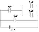
In the adjoining figure, four capacitors are shown with their respective capacities and the P.D. applied. The charge and the P.D. across the \[4\mu F\] capacitor will be
A)
\[600\mu C;\ 150\ volts\] done
clear
B)
\[300\mu C;\ 75\ volts\] done
clear
C)
\[800\mu C;\ 200\ volts\] done
clear
D)
\[580\mu C;\ 145\ volts\] done
clear
View Solution play_arrow
-
question_answer37)
Three identical capacitors are combined differently. For the same voltage to each combination, the one that stores the greatest energy is [MP PMT 1995]
A)
Two in parallel and the third in series with it done
clear
B)
Three in series done
clear
C)
Three in parallel done
clear
D)
Two in series and third in parallel with it done
clear
View Solution play_arrow
-
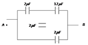
question_answer38)
Two capacitors each of capacity \[2\mu F\] are connected in parallel. This system is connected in series with a third capacitor of \[12\mu F\] capacity. The equivalent capacity of the system will be [MP PET 1990; MP PMT 1990]
A)
\[16\mu F\] done
clear
B)
\[13\mu F\] done
clear
C)
\[4\mu F\] done
clear
D)
\[3\mu F\] done
clear
View Solution play_arrow
-
question_answer39)
A \[4\mu F\]condenser is connected in parallel to another condenser of\[8\mu F\]. Both the condensers are then connected in series with a \[12\mu F\] condenser and charged to \[20\ volts\]. The charge on the plate of \[4\mu F\]condenser is [MP PET 1989]
A)
\[3.3\mu C\] done
clear
B)
\[40\mu C\] done
clear
C)
\[80\mu C\] done
clear
D)
\[240\mu C\] done
clear
View Solution play_arrow
-
question_answer40)
A capacitor having capacitance \[C\] is charged to a voltage \[V\]. It is then removed and connected in parallel with another identical capacitor which is uncharged. The new charge on each capacitor is now [MP PET 1990]
A)
CV done
clear
B)
CV / 2 done
clear
C)
2 CV done
clear
D)
CV / 4 done
clear
View Solution play_arrow
-
question_answer41)
In the connections shown in the adjoining figure, the equivalent capacity between \[A\] and \[B\] will be
A)
\[10.8\mu F\] done
clear
B)
\[69\mu F\] done
clear
C)
\[15\mu F\] done
clear
D)
\[10\mu F\] done
clear
View Solution play_arrow
-
question_answer42)
\[2\mu F\]capacitance has potential difference across its two terminals \[200\ volts\]. It is disconnected with battery and then another uncharged capacitance is connected in parallel to it, then P.D. becomes\[20\ volts\]. Then the capacity of another capacitance will be [CPMT 1991; DPMT 2001]
A)
\[2\mu F\] done
clear
B)
\[4\mu F\] done
clear
C)
\[18\mu F\] done
clear
D)
\[10\mu F\] done
clear
View Solution play_arrow
-
question_answer43)
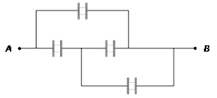
The resultant capacitance between \[A\] and \[B\] in the following figure is equal to
A)
\[1\mu F\] done
clear
B)
\[3\mu F\] done
clear
C)
\[2\mu F\] done
clear
D)
\[1.5\mu fF\] done
clear
View Solution play_arrow
-
question_answer44)
In the following circuit, the resultant capacitance between \[A\] and \[B\] is 1mF. Then value of \[C\] is [IIT 1977]
A)
\[\frac{32}{11}\mu F\] done
clear
B)
\[\frac{11}{32}\mu F\] done
clear
C)
\[\frac{23}{32}\mu F\] done
clear
D)
\[\frac{32}{23}\mu F\] done
clear
View Solution play_arrow
-
question_answer45)
Two dielectric slabs of constant \[{{K}_{1}}\] and \[{{K}_{2}}\] have been filled in between the plates of a capacitor as shown below. What will be the capacitance of the capacitor [MNR 1985; MP PET 1999; DCE 2002]
A)
\[\frac{2{{\varepsilon }_{0}}A}{2}({{K}_{1}}+{{K}_{2}})\] done
clear
B)
\[\frac{2{{\varepsilon }_{0}}A}{2}\left( \frac{{{K}_{1}}+{{K}_{2}}}{{{K}_{1}}\times {{K}_{2}}} \right)\] done
clear
C)
\[\frac{2{{\varepsilon }_{0}}A}{2}\left( \frac{{{K}_{1}}\times {{K}_{2}}}{{{K}_{1}}+{{K}_{2}}} \right)\] done
clear
D)
\[\frac{2{{\varepsilon }_{0}}A}{d}\left( \frac{{{K}_{1}}\times {{K}_{2}}}{{{K}_{1}}+{{K}_{2}}} \right)\] done
clear
View Solution play_arrow
-
question_answer46)
What is the equivalent capacitance between \[A\]and\[B\] in the given figure (all are in farad) [BHU 1997]
A)
\[\frac{13}{18}F\] done
clear
B)
\[\frac{48}{13}F\] done
clear
C)
\[\frac{1}{31}F\] done
clear
D)
\[\frac{240}{71}F\] done
clear
View Solution play_arrow
-
question_answer47)
A condenser having a capacity of 6mF is charged to 100 V and is then joined to an uncharged condenser of \[14\mu F\] and then removed. The ratio of the charges on 6mF and 14mF and the potential of 6mF will be [MP PMT 1991]
A)
\[\frac{6}{14}\] and \[50\ volt\] done
clear
B)
\[\frac{14}{6}\] and \[30\ volt\] done
clear
C)
\[\frac{6}{14}\] and \[30\ volt\] done
clear
D)
\[\frac{14}{6}\] and 0\[volt\] done
clear
View Solution play_arrow
-
question_answer48)
\[0.2F\]capacitor is charged to \[600\,V\]by a battery. On removing the battery, it is connected with another parallel plate condenser of 1F. The potential decreases to [MNR 1978; MP PET 2002]
A)
\[100\ volts\] done
clear
B)
\[120\ volts\] done
clear
C)
\[300\ volts\] done
clear
D)
\[600\ volts\] done
clear
View Solution play_arrow
-
question_answer49)
In the circuit shown in the figure, the potential difference across the 4.5mF capacitor is [MP PET 1992; RPET 2001; BVP 2003]
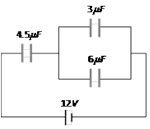
A)
\[\frac{8}{3}\ volts\] done
clear
B)
4 \[volts\] done
clear
C)
6\[volts\] done
clear
D)
8 \[volts\] done
clear
View Solution play_arrow
-
question_answer50)
Minimum number of capacitors of \[2\mu F\] capacitance each required to obtain a capacitor of \[5\mu F\] will be [MP PET 1992]
A)
Three done
clear
B)
Four done
clear
C)
Five done
clear
D)
Six done
clear
View Solution play_arrow
-
question_answer51)
A condenser of capacitance \[10\mu F\] has been charged to 100\[volts\]. It is now connected to another uncharged condenser in parallel. The common potential becomes 40\[volts\]. The capacitance of another condenser is [MP PET 1992]
A)
\[15\mu F\] done
clear
B)
\[5\mu F\] done
clear
C)
\[10\mu F\] done
clear
D)
\[16.6\mu F\] done
clear
View Solution play_arrow
-
question_answer52)
. A capacitor \[4\mu F\]charged to 50 \[V\] is connected to another capacitor of \[2\mu F\] charged to 100 \[V\] with plates of like charges connected together. The total energy before and after connection in multiples of \[({{10}^{-2}}J)\] is [MP PMT 1992]
A)
1.5 and 1.33 done
clear
B)
1.33 and 1.5 done
clear
C)
3.0 and 2.67 done
clear
D)
2.67 and 3.0 done
clear
View Solution play_arrow
-
question_answer53)
Two capacitors of 3pF and 6pF are connected in series and a potential difference of 5000\[V\] is applied across the combination. They are then disconnected and reconnected in parallel. The potential between the plates is [MP PMT 1992]
A)
2250\[V\] done
clear
B)
2222\[V\] done
clear
C)
\[2.25\times {{10}^{6}}V\] done
clear
D)
\[1.1\times {{10}^{6}}V\] done
clear
View Solution play_arrow
-
question_answer54)
Two identical parallel plate capacitors are connected in series to a battery of 100\[V\]. A dielectric slab of dielectric constant 4.0 is inserted between the plates of second capacitor. The potential difference across the capacitors will now be respectively [MP PMT 1992]
A)
50 V, 50 V done
clear
B)
80 V, 20 V done
clear
C)
20 V, 80 V done
clear
D)
75 V, 25 V done
clear
View Solution play_arrow
-
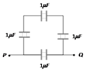
question_answer55)
Four capacitors are connected as shown in the equivalent capacitance between the points P and Q is [MP PET 1983; MP PMT 1992; UPSEAT 1999]
A)
\[4\mu F\] done
clear
B)
\[\frac{1}{4}\mu F\] done
clear
C)
\[\frac{3}{4}\mu F\] done
clear
D)
\[\frac{4}{3}\mu F\] done
clear
View Solution play_arrow
-
question_answer56)
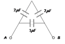
The total capacity of the system of capacitors shown in the adjoining figure between the points \[A\] and \[B\] is [Pantnagar 1987; SCRA 1996; MP PMT 2002]
A)
\[1\mu F\] done
clear
B)
\[2\mu F\] done
clear
C)
\[3\mu F\] done
clear
D)
\[4\mu F\] done
clear
View Solution play_arrow
-
question_answer57)
The equivalent capacitance between \[A\] and \[B\] in the figure is\[1\mu F\]. Then the value of capacitance \[C\] is [MP PET 1994]
A)
\[1.4\mu F\] done
clear
B)
\[2.5\mu F\] done
clear
C)
\[3.5\mu F\] done
clear
D)
\[1.2\mu F\] done
clear
View Solution play_arrow
-
question_answer58)
A condenser of capacity \[{{C}_{1}}\]is charged to a potential \[{{V}_{0}}\]. The electrostatic energy stored in it is \[{{U}_{0}}\]. It is connected to another uncharged condenser of capacity \[{{C}_{2}}\] in parallel. The energy dissipated in the process is [MP PMT 1994]
A)
\[\frac{{{C}_{2}}}{{{C}_{1}}+{{C}_{2}}}{{U}_{0}}\] done
clear
B)
\[\frac{{{C}_{1}}}{{{C}_{1}}+{{C}_{2}}}{{U}_{0}}\] done
clear
C)
\[\left( \frac{{{C}_{1}}-{{C}_{2}}}{{{C}_{1}}+{{C}_{2}}} \right){{U}_{0}}\] done
clear
D)
\[\frac{{{C}_{1}}{{C}_{2}}}{2({{C}_{1}}+{{C}_{2}})}{{U}_{0}}\] done
clear
View Solution play_arrow
-
question_answer59)
Three capacitors each of \[6\mu F\] are available. The minimum and maximum capacitances which may be obtained are [MP PMT 1994]
A)
\[6\mu F,\ 18\mu F\] done
clear
B)
\[3\mu F,\ 12\mu F\] done
clear
C)
\[2\mu F,\ 12\mu F\] done
clear
D)
\[2\mu F,\ 18\mu F\] done
clear
View Solution play_arrow
-
question_answer60)

Four capacitors are connected in a circuit as shown in the figure. The effective capacitance in \[\mu F\]between points A and B will be [MP PET 1996; Pb. PMT 2001; DPMT 2003]
A)
\[\frac{28}{9}\] done
clear
B)
4 done
clear
C)
5 done
clear
D)
18 done
clear
View Solution play_arrow
-
question_answer61)
100 capacitors each having a capacity of \[10\mu F\]are connected in parallel and are charged by a potential difference of \[100\,kV\]. The energy stored in the capacitors and the cost of charging them, if electrical energy costs \[108\ paise\ per\ kWh\], will be [MP PET 1996; DPMT 2001]
A)
\[{{10}^{7}}\ joule\] and \[300\ paise\] done
clear
B)
\[5\times {{10}^{6}}joule\] and\[300\ paise\] done
clear
C)
\[5\times {{10}^{6}}joule\] and\[150\ paise\] done
clear
D)
\[{{10}^{7}}\,joule\]and \[150\ paise\] done
clear
View Solution play_arrow
-
question_answer62)
Three capacitors of \[2.0,\ 3.0\] and \[6.0\ \mu F\] are connected in series to a \[10V\] source. The charge on the \[3.0\mu F\] capacitor is [MP PMT 1996; RPMT 1999; Pb. PMT 2001]
A)
\[5\mu C\] done
clear
B)
\[10\mu C\] done
clear
C)
\[12\mu C\] done
clear
D)
\[15\mu C\] done
clear
View Solution play_arrow
-
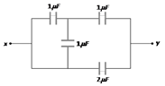
question_answer63)
Four capacitors are connected as shown in the figure. Their capacities are indicated in the figure. The effective capacitance between points \[x\] and \[y\] is (in\[\mu F\]) [RPET 1997]
A)
\[\frac{5}{6}\] done
clear
B)
\[\frac{7}{6}\] done
clear
C)
\[\frac{8}{3}\] done
clear
D)
2 done
clear
View Solution play_arrow
-
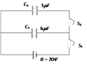
question_answer64)
In the circuit shown here \[{{C}_{1}}=6\mu F,\ {{C}_{2}}=3\mu F\]and battery\[B=20V\]. The switch \[{{S}_{1}}\] is first closed. It is then opened and afterwards \[{{S}_{2}}\] is closed. What is the charge finally on \[{{C}_{2}}\]
A)
\[120\mu C\] done
clear
B)
\[80\mu C\] done
clear
C)
\[40\mu C\] done
clear
D)
\[20\mu C\] done
clear
View Solution play_arrow
-
question_answer65)
The effective capacitance between the points \[P\] and \[Q\] of the arrangement shown in the figure is [MP PET 1997]
A)
\[\frac{1}{2}\mu F\] done
clear
B)
\[1\mu F\] done
clear
C)
\[2\mu F\] done
clear
D)
\[1.33\mu F\] done
clear
View Solution play_arrow
-
question_answer66)
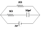
A capacitor of capacitance \[5\mu F\] is connected as shown in the figure. The internal resistance of the cell is\[0.5\Omega \]. The amount of charge on the capacitor plate is [MP PET 1997]
A)
\[0\mu C\] done
clear
B)
\[5\mu C\] done
clear
C)
\[10\mu C\] done
clear
D)
\[25\mu C\] done
clear
View Solution play_arrow
-
question_answer67)
Choose the incorrect statement from the following: When two identical capacitors are charged individually to different potentials and connected parallel to each other after disconnecting them from the source [MP PET 1997]
A)
Net charge equals the sum of initial charges done
clear
B)
The net energy stored in the two capacitors is less than the sum of the initial individual energies done
clear
C)
The net potential difference across them is different from the sum of the individual initial potential difference done
clear
D)
The net potential difference across them equals the sum of the individual initial potential differences done
clear
View Solution play_arrow
-
question_answer68)
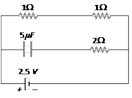
A \[10\mu F\] capacitor and a \[20\mu F\] capacitor are connected in series across a \[200\ V\] supply line. The charged capacitors are then disconnected from the line and reconnected with their positive plates together and negative plates together and no external voltage is applied. What is the potential difference across each capacitor [MP PET 1997]
A)
\[\frac{400}{9}\text{V}\] done
clear
B)
\[\frac{800}{9}V\] done
clear
C)
\[400\ V\] done
clear
D)
\[200\,V\] done
clear
View Solution play_arrow
-
question_answer69)
Two condensers \[{{C}_{1}}\]and \[{{C}_{2}}\] in a circuit are joined as shown in figure. The potential of point \[A\] is \[{{V}_{1}}\] and that of \[B\] is \[{{V}_{2}}\]. The potential of point \[D\] will be [MP PMT 1997]
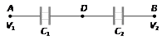
A)
\[\frac{1}{2}({{V}_{1}}+{{V}_{2}})\] done
clear
B)
\[\frac{{{C}_{2}}{{V}_{1}}+{{C}_{1}}{{V}_{2}}}{{{C}_{1}}+{{C}_{2}}}\] done
clear
C)
\[\frac{{{C}_{1}}{{V}_{1}}+{{C}_{2}}{{V}_{2}}}{{{C}_{1}}+{{C}_{2}}}\] done
clear
D)
\[\frac{{{C}_{2}}{{V}_{1}}-{{C}_{1}}{{V}_{2}}}{{{C}_{1}}+{{C}_{2}}}\] done
clear
View Solution play_arrow
-
question_answer70)
To obtain \[3\mu F\] capacity from three capacitors of \[2\mu F\]each, they will be arranged [MP PMT/PET 1998]
A)
All the three in series done
clear
B)
All the three in parallel done
clear
C)
Two capacitors in series and the third in parallel with the combination of first two done
clear
D)
Two capacitors in parallel and the third in series with the combination of first two done
clear
View Solution play_arrow
-
question_answer71)
A \[10\mu F\] capacitor is charged to a potential difference of \[50\ V\]and is connected to another uncharged capacitor in parallel. Now the common potential difference becomes \[20\ volt\]. The capacitance of second capacitor is [MP PET 1999; DPMT 2000]
A)
\[10\mu F\] done
clear
B)
\[20\mu F\] done
clear
C)
\[30\mu F\] done
clear
D)
\[15\mu F\] done
clear
View Solution play_arrow
-
question_answer72)
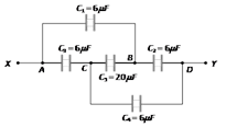
What is the effective capacitance between points \[X\]and \[Y\] [CBSE PMT 1999]
A)
\[24\mu F\] done
clear
B)
\[18\mu F\] done
clear
C)
\[12\mu F\] done
clear
D)
\[6\mu F\] done
clear
View Solution play_arrow
-
question_answer73)
The combined capacity of the parallel combination of two capacitors is four times their combined capacity when connected in series. This means that [EAMCET 1994]
A)
Their capacities are equal done
clear
B)
Their capacities are \[1\mu F\]and \[2\mu F\] done
clear
C)
Their capacities are \[0.5\mu F\] and \[1\mu F\] done
clear
D)
Their capacities are infinite done
clear
View Solution play_arrow
-
question_answer74)
The charge on a capacitor of capacitance \[10\mu F\]connected as shown in the figure is [AMU 1995]
A)
\[20\mu C\] done
clear
B)
\[15\mu C\] done
clear
C)
\[10\mu C\] done
clear
D)
Zero done
clear
View Solution play_arrow
-
question_answer75)
The resultant capacitance of given circuit is [RPET 1997]
A)
\[3C\] done
clear
B)
\[2C\] done
clear
C)
\[C\] done
clear
D)
\[\frac{C}{3}\] done
clear
View Solution play_arrow
-
question_answer76)
Three plates\[A,\ B,\ C\]each of area \[50\,c{{m}^{2}}\] have separation \[3mm\] between \[A\]and \[B\] and \[3mm\] between \[B\] and \[C\]The energy stored when the plates are fully charged is [SCRA 1996]
A)
\[1.6\times {{10}^{-9}}J\] done
clear
B)
\[2.1\times {{10}^{-9}}J\] done
clear
C)
\[5\times {{10}^{-9}}J\] done
clear
D)
\[7\times {{10}^{-9}}J\] done
clear
View Solution play_arrow
-
question_answer77)
A capacitor of \[20\mu F\] is charged to \[500\ volts\] and connected in parallel with another capacitor of \[10\mu F\] and charged to \[200\ volts\]. The common potential is [BHU 1997; CBSE PMT 2000; MH CET 1999; BHU 2004]
A)
\[200\ volts\] done
clear
B)
\[300\ volts\] done
clear
C)
\[\text{400 }volts\] done
clear
D)
\[\text{500 }volts\] done
clear
View Solution play_arrow
-
question_answer78)
In the given network capacitance, \[{{C}_{1}}=10\mu \,F,\,{{C}_{2}}=5\mu \,F\] and \[{{C}_{3}}=4\mu \,F\]. What is the resultant capacitance between A and B [Pb. PMT 1999]
A)
2.2\[\mu \,F\] done
clear
B)
3.2\[\mu \,F\] done
clear
C)
1.2\[\mu \,F\] done
clear
D)
4.7\[\mu \,F\] done
clear
View Solution play_arrow
-
question_answer79)
The equivalent capacitance between A and B is [RPMT 1999]
A)
2\[\mu \,F\] done
clear
B)
3\[\mu \,F\] done
clear
C)
5\[\mu \,F\] done
clear
D)
0.5\[\mu \,F\] done
clear
View Solution play_arrow
-
question_answer80)
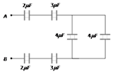
The capacitance between the points A and B in the given circuit will be [AMU (Med.) 1999; MH CET 1999; Pb. PET 2002; BCECE 2005]
A)
1\[\mu \,F\] done
clear
B)
2\[\mu \,F\] done
clear
C)
3\[\mu \,F\] done
clear
D)
4\[\mu \,F\] done
clear
View Solution play_arrow
-
question_answer81)
The equivalent capacitance of three capacitors of capacitance \[{{C}_{1}},{{C}_{2}}\] and \[{{C}_{3}}\] are connected in parallel is 12 units and product \[{{C}_{1}}.{{C}_{2}}.{{C}_{3}}=48\]. When the capacitors \[{{C}_{1}}\] and \[{{C}_{2}}\] are connected in parallel, the equivalent capacitance is 6 units. Then the capacitance are [KCET 1999]
A)
2, 3, 7 done
clear
B)
1.5, 2.5, 8 done
clear
C)
1, 5, 6 done
clear
D)
4, 2, 6 done
clear
View Solution play_arrow
-
question_answer82)
In the circuit shown in figure, each capacitor has a capacity of \[3\mu F\]. The equivalent capacity between A and B is [MP PMT 2000]
A)
\[\frac{3}{4}\mu F\] done
clear
B)
\[3\mu F\] done
clear
C)
\[6\mu F\] done
clear
D)
\[5\mu F\] done
clear
View Solution play_arrow
-
question_answer83)
What is the effective capacitance between A and B in the following figure [AMU (Engg.) 2000]
A)
\[1\mu \,F\] done
clear
B)
\[2\mu \,F\] done
clear
C)
\[1.5\mu \,F\] done
clear
D)
\[2.5\mu \,F\] done
clear
View Solution play_arrow
-
question_answer84)
A potential difference of 300 volts is applied to a combination of 2.0mF and 8.0mF capacitors connected in series. The charge on the 2.0mF capacitor is [MP PMT 2000]
A)
\[2.4\times {{10}^{-4}}\]C done
clear
B)
\[4.8\times {{10}^{-4}}\]C done
clear
C)
\[7.2\times {{10}^{-4}}\]C done
clear
D)
\[9.6\times {{10}^{-4}}\]C done
clear
View Solution play_arrow
-
question_answer85)
Ten capacitor are joined in parallel and charged with a battery up to a potential V. They are then disconnected from battery and joined again in series then the potential of this combination will be [RPET 2000]
A)
V done
clear
B)
10V done
clear
C)
5V done
clear
D)
2V done
clear
View Solution play_arrow
-
question_answer86)
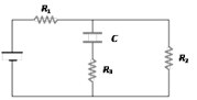
In the circuit here, the steady state voltage across capacitor C is a fraction of the battery e.m.f. The fraction is decided by [AMU (Engg.) 2000]
A)
\[{{R}_{\text{1}}}\] only done
clear
B)
\[{{R}_{\text{1}}}\] and \[{{R}_{\text{2}}}\] only done
clear
C)
\[{{R}_{1}}\] and \[{{R}_{3}}\] only done
clear
D)
\[{{R}_{1}}\],\[{{R}_{2}}\] and \[{{R}_{3}}\] done
clear
View Solution play_arrow
-
question_answer87)
A parallel plate capacitor of area A, plate separation d and capacitance C is filled with three different dielectric materials having dielectric constants \[{{k}_{1}},{{k}_{2}}\] and \[{{k}_{3}}\] as shown. If a single dielectric material is to be used to have the same capacitance C in this capacitor, then its dielectric constant k is given by [IIT-JEE Screening 2000]
A)
\[\frac{1}{k}=\frac{1}{{{k}_{1}}}+\frac{1}{{{k}_{2}}}+\frac{1}{2{{k}_{3}}}\] done
clear
B)
\[\frac{1}{k}=\frac{1}{{{k}_{1}}+{{k}_{2}}}+\frac{1}{2{{k}_{3}}}\] done
clear
C)
\[k=\frac{{{k}_{1}}{{k}_{2}}}{{{k}_{1}}+{{k}_{2}}}+2{{k}_{3}}\] done
clear
D)
\[k={{k}_{1}}+{{k}_{2}}+2{{k}_{3}}\] done
clear
View Solution play_arrow
-
question_answer88)
Two capacitors A and B are connected in series with a battery as shown in the figure. When the switch S is closed and the two capacitors get charged fully, then [MP PET 2000]
A)
The potential difference across the plates of A is 4V and across the plates of B is 6V done
clear
B)
The potential difference across the plates of A is 6V and across the plates of B is 4V done
clear
C)
The ratio of electrical energies stored in A and B is 2 : 3 done
clear
D)
The ratio of charges on A and B is 3 : 2 done
clear
View Solution play_arrow
-
question_answer89)
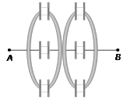
In the figure, three capacitors each of capacitance 6\[pF\] are connected in series. The total capacitance of the combination will be [MH CET 2000; CPMT 2001]
A)
\[9\times {{10}^{-12}}\,F\] done
clear
B)
\[6\times {{10}^{-12}}\,F\] done
clear
C)
\[3\times {{10}^{-12}}\,F\] done
clear
D)
\[2\times {{10}^{-12}}\,F\] done
clear
View Solution play_arrow
-
question_answer90)
Equivalent capacitance between A and B is [DCE 2001]
A)
\[8\,\mu \,F\] done
clear
B)
\[6\,\mu \,F\] done
clear
C)
\[26\,\mu \,F\] done
clear
D)
\[10/3\,\mu \,F\] done
clear
View Solution play_arrow
-
question_answer91)
Two capacitors of \[10\,\mu \,F\] and \[20\,\mu \,F\] are connected in series with a 30V battery. The charge on the capacitors will be, respectively [AMU (Engg.) 2001]
A)
100\[\mu \,C\], 200\[\mu \,C\] done
clear
B)
200\[\mu \,C\], 100 \[\mu \,C\] done
clear
C)
100\[\mu \,C\], 100\[\mu \,C\] done
clear
D)
200\[\mu \,C\], 200\[\mu \,C\] done
clear
View Solution play_arrow
-
question_answer92)
In the figure a capacitor is filled with dielectrics. The resultant capacitance is [UPSEAT 2001]
A)
\[\frac{2{{\varepsilon }_{0}}A}{d}\,\left[ \frac{1}{{{k}_{1}}}+\frac{1}{{{k}_{2}}}+\frac{1}{{{k}_{3}}} \right]\] done
clear
B)
\[\frac{{{\varepsilon }_{0}}A}{d}\,\left[ \frac{1}{{{k}_{1}}}+\frac{1}{{{k}_{2}}}+\frac{1}{{{k}_{3}}} \right]\] done
clear
C)
\[\frac{2{{\varepsilon }_{0}}A}{d}\,\left[ {{k}_{1}}+{{k}_{2}}+{{k}_{3}} \right]\] done
clear
D)
None of these done
clear
View Solution play_arrow
-
question_answer93)
Three capacitors of capacitance \[3\mu \,F,\,10\mu \,F\,\] and \[15\mu \,F\,\] are connected in series to a voltage source of 100V. The charge on \[15\mu \,F\,\]is [Pb. PMT 1999; AIIMS 2000; CPMT 2001]
A)
\[50\,\mu \,C\] done
clear
B)
\[100\,\mu \,C\] done
clear
C)
\[200\,\mu \,C\] done
clear
D)
\[280\,\mu \,C\] done
clear
View Solution play_arrow
-
question_answer94)
Consider a parallel plate capacitor of \[10\mu \,F\] (micro-farad) with air filled in the gap between the plates. Now one half of the space between the plates is filled with a dielectric of dielectric constant 4, as shown in the figure. The capacity of the capacitor changes to [AFMC 2001; MP PET 2001]
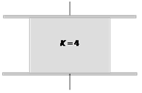
A)
\[25\,\mu \,F\] done
clear
B)
\[20\,\mu \,F\] done
clear
C)
\[40\,\mu \,F\] done
clear
D)
\[5\,\mu \,F\] done
clear
View Solution play_arrow
-
question_answer95)
The combination of capacitors with \[{{C}_{1}}=3\mu \,F,\,{{C}_{2}}=4\mu \,F\] and \[{{C}_{3}}=2\mu \,F\] is charged by connecting AB to a battery. Consider the following statements I. Energy stored in \[{{C}_{1}}\]= Energy stored in \[{{C}_{2}}\] + Energy stored in \[{{C}_{3}}\] II. Charge on C1 = Charge on C2 + Charge on C3 III. Potential drop across C1 = Potential drop across C2 = Potential drop across C3 Which of these is/are correct [AMU (Med.) 2001]
A)
I and II done
clear
B)
II only done
clear
C)
I and III done
clear
D)
III only done
clear
View Solution play_arrow
-
question_answer96)
Two capacitors \[{{C}_{1}}=2\mu \,F\] and \[{{C}_{2}}\,=\,6\,\mu \,F\] in series, are connected in parallel to a third capacitor \[{{C}_{3}}=\,4\,\mu \,F\]. This arrangement is then connected to a battery of e.m.f. = 2V, as shown in the figure. How much energy is lost by the battery in charging the capacitors [MP PET 2001]
A)
\[22\times {{10}^{-6}}\,J\] done
clear
B)
\[11\times {{10}^{-6}}\,J\] done
clear
C)
\[\left( \frac{32}{3} \right)\times {{10}^{-6}}\,J\] done
clear
D)
\[\left( \frac{16}{3} \right)\times {{10}^{-6}}\,J\] done
clear
View Solution play_arrow
-
question_answer97)
A 20F capacitor is charged to 5V and isolated. It is then connected in parallel with an uncharged 30F capacitor. The decrease in the energy of the system will be [EAMCET 2001]
A)
25 J done
clear
B)
200 J done
clear
C)
125 J done
clear
D)
150 J done
clear
View Solution play_arrow
-
question_answer98)
A parallel plate capacitor has capacitance C. If it is equally filled with parallel layers of materials of dielectric constants \[{{K}_{\text{1}}}\] and \[{{K}_{\text{2}}}\] its capacity becomes \[{{C}_{\text{1}}}\]. The ratio of \[{{C}_{\text{1}}}\] to C is [MP PMT 2001]
A)
\[{{K}_{1}}+{{K}_{2}}\] done
clear
B)
\[\frac{{{K}_{1}}{{K}_{2}}}{{{K}_{1}}-{{K}_{2}}}\] done
clear
C)
\[\frac{{{K}_{1}}+{{K}_{2}}}{{{K}_{1}}{{K}_{2}}}\] done
clear
D)
\[\frac{2{{K}_{1}}{{K}_{2}}}{{{K}_{1}}+{{K}_{2}}}\] done
clear
View Solution play_arrow
-
question_answer99)
The equivalent capacitance in the circuit between A and B will be [UPSEAT 2002]
A)
\[1\,\mu F\] done
clear
B)
\[2\,\mu F\] done
clear
C)
\[3\,\mu F\] done
clear
D)
\[\frac{1}{3}\,\mu F\] done
clear
View Solution play_arrow
-
question_answer100)
The equivalent capacitance between A and B is [Pb. PMT 2002]
A)
\[\frac{C}{4}\] done
clear
B)
\[\frac{3C}{4}\] done
clear
C)
\[\frac{C}{3}\] done
clear
D)
\[\frac{4C}{3}\] done
clear
View Solution play_arrow
-
question_answer101)
The effective capacity between A and B in the figure given is [Kerala PMT 2002]
A)
\[\frac{43}{24}\mu F\] done
clear
B)
\[\frac{24}{43}\mu F\] done
clear
C)
\[\frac{43}{12}\mu F\] done
clear
D)
\[\frac{12}{43}\mu F\] done
clear
View Solution play_arrow
-
question_answer102)
In the given figure the capacitors \[{{C}_{1}},{{C}_{3}},{{C}_{4}},{{C}_{5}}\] have a capacitance 4mF each if the capacitor C2 has a capacitance 10mF, then effective capacitance between A and B will be [AIIMS 2002]
A)
2mF done
clear
B)
4mF done
clear
C)
6mF done
clear
D)
8mF done
clear
View Solution play_arrow
-
question_answer103)
Two capacitors \[{{C}_{\text{1}}}\] and \[{{C}_{\text{2}}}=\text{ 2}{{C}_{\text{1}}}\] are connected in a circuit with a switch between them as shown in the figure. Initially the switch is open and \[{{C}_{\text{1}}}\] holds charge Q. The switch is closed. At steady state, the charge on each capacitor will be [Orissa JEE 2002]
A)
\[Q,\,2Q\] done
clear
B)
\[Q/3,\,2Q/3\] done
clear
C)
\[3Q/2,\,3Q\] done
clear
D)
\[2Q/3,\,4Q/3\] done
clear
View Solution play_arrow
-
question_answer104)
Three capacitors of \[2\mu F,\,3\mu F\] and \[6\mu F\] are joined in series and the combination is charged by means of a 24 volt battery. The potential difference between the plates of the \[6\mu F\] capacitor is [MP PMT 2002]
A)
4 volt done
clear
B)
6 volt done
clear
C)
8 volt done
clear
D)
10 volt done
clear
View Solution play_arrow
-
question_answer105)
Two capacitors of capacitances \[3\mu \,F\] and \[6\mu F\] are charged to a potential of 12 V each. They are now connected to each other, with the positive plate of each joined to the negative plate of the other. The potential difference across each will be [KCET 2002]
A)
6 volt done
clear
B)
4 volt done
clear
C)
3 volt done
clear
D)
Zero done
clear
View Solution play_arrow
-
question_answer106)
Two identical capacitors, have the same capacitance C. One of them is charged to potential \[{{V}_{1}}\] and the other to \[{{V}_{2}}\]. The negative ends of the capacitors are connected together. When the positive ends are also connected, the decrease in energy of the combined system is [IIT-JEE (Screening) 2002]
A)
\[\frac{1}{4}C(V_{1}^{2}-V_{2}^{2})\] done
clear
B)
\[\frac{1}{4}C(V_{1}^{2}+V_{2}^{2})\] done
clear
C)
\[\frac{1}{4}C{{\left( {{V}_{1}}-{{V}_{2}} \right)}^{2}}\] done
clear
D)
\[\frac{1}{4}C{{\left( {{V}_{1}}+{{V}_{2}} \right)}^{2}}\] done
clear
View Solution play_arrow
-
question_answer107)
A capacitor of 10mF charged up to 250 volts is connected in parallel with another capacitor of 5mF charged up to 100 volts. The common potential is [BHU 2002]
A)
500 V done
clear
B)
400 V done
clear
C)
300 V done
clear
D)
200 V done
clear
View Solution play_arrow
-
question_answer108)
Two capacitors of 1mF and 2mF are connected in series, the resultant capacitance will be [MP PET 2002]
A)
\[4\mu \,F\] done
clear
B)
\[\frac{2}{3}\mu \,F\] done
clear
C)
\[\frac{3}{2}\mu \,F\] done
clear
D)
\[3\mu \,F\] done
clear
View Solution play_arrow
-
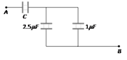
question_answer109)
The charge on any one of the \[2\mu \,F\] capacitors and \[1\mu \,F\] capacitor will be given respectively (in \[\mu \,C\]) as [AMU (Med.) 2002]
A)
1, 2 done
clear
B)
2, 1 done
clear
C)
1, 1 done
clear
D)
2, 2 done
clear
View Solution play_arrow
-
question_answer110)
When two identical capacitors are in series have 3mF capacitance and when parallel 12mF. What is the capacitance of each [DPMT 2002]
A)
\[6\mu \,F\] done
clear
B)
\[3\mu \,F\] done
clear
C)
\[12\mu \,F\] done
clear
D)
\[9\mu \,F\] done
clear
View Solution play_arrow
-
question_answer111)
In the circuit as shown in the figure the effective capacitance between A and B is [KCET 2003]
A)
\[3\,\mu \,F\] done
clear
B)
\[2\,\mu \,F\] done
clear
C)
\[4\,\mu \,F\] done
clear
D)
\[8\,\mu \,F\] done
clear
View Solution play_arrow
-
question_answer112)
Four equal capacitors, each of capacity C, are arranged as shown. The effective capacitance between A and B is [MP PET 2003]
A)
\[\frac{5}{8}C\] done
clear
B)
\[\frac{3}{5}C\] done
clear
C)
\[\frac{5}{3}C\] done
clear
D)
C done
clear
View Solution play_arrow
-
question_answer113)
In the figure shown, the effective capacitance between the points A and B, if each has capacitance C, is [MP PET 2003]
A)
2C done
clear
B)
\[\frac{C}{5}\] done
clear
C)
5C done
clear
D)
\[\frac{C}{2}\] done
clear
View Solution play_arrow
-
question_answer114)
Three capacitors each of capacity \[4\mu \,F\] are to be connected in such a way that the effective capacitance is \[6\,\mu \,F\]. This can be done by [CBSE PMT 2003]
A)
Connecting them in parallel done
clear
B)
Connecting two in series and one in parallel done
clear
C)
Connecting two in parallel and one in series done
clear
D)
Connecting all of them in series done
clear
View Solution play_arrow
-
question_answer115)
Three capacitors of capacitance \[3\,\mu \,F\] are connected in a circuit. Then their maximum and minimum capacitances will be [RPET 2003]
A)
\[9\,\mu \,F\], \[1\,\mu \,F\] done
clear
B)
\[8\,\mu \,F\], \[2\,\mu \,F\] done
clear
C)
\[9\,\mu \,F\], \[0\,\mu \,F\] done
clear
D)
\[3\,\mu \,F\], \[2\,\mu \,F\] done
clear
View Solution play_arrow
-
question_answer116)
A capacitor of capacity \[{{C}_{1}}\]is charged upto V volt and then connected to an uncharged capacitor of capacity \[{{C}_{2}}\]. Then final potential difference across each will be [MP PET 2000; CBSE PMT 2002; MP PET 2003]
A)
\[\frac{{{C}_{2}}V}{{{C}_{1}}+{{C}_{2}}}\] done
clear
B)
\[\left( 1+\frac{{{C}_{2}}}{{{C}_{1}}} \right)\,V\] done
clear
C)
\[\frac{{{C}_{1}}V}{{{C}_{1}}+{{C}_{2}}}\] done
clear
D)
\[\left( 1-\frac{{{C}_{2}}}{{{C}_{1}}} \right)\,V\] done
clear
View Solution play_arrow
-
question_answer117)
A series combination of three capacitors of capacities \[1\mu \,F,\,2\,\mu \,F\] and \[8\mu \,F\] is connected to a battery of e.m.f. 13 volt. The potential difference across the plates of \[\,2\,\mu \,F\] capacitor will be [MP PET 2003]
A)
\[1V\] done
clear
B)
\[8V\] done
clear
C)
\[4V\] done
clear
D)
\[\frac{13}{3}V\] done
clear
View Solution play_arrow
-
question_answer118)
Two capacitors of capacitance 2mF and \[3\mu F\] are joined in series. Outer plate first capacitor is at 1000 volt and outer plate of second capacitor is earthed (grounded). Now the potential on inner plate of each capacitor will be [MP PMT 2003]
A)
700 Volt done
clear
B)
200 Volt done
clear
C)
600 Volt done
clear
D)
400 Volt done
clear
View Solution play_arrow
-
question_answer119)
In the figure a potential of + 1200 V is given to point A and point B is earthed, what is the potential at the point P [MP PMT 2004]
A)
100 V done
clear
B)
200 V done
clear
C)
400 V done
clear
D)
600 V done
clear
View Solution play_arrow
-
question_answer120)
All six capacitors shown are identical, Each can withstand maximum 200 volts between its terminals. The maximum voltage that can be safely applied between A and B is [MP PMT 2004]
A)
1200 V done
clear
B)
400 V done
clear
C)
800 V done
clear
D)
200 V done
clear
View Solution play_arrow
-
question_answer121)
The charge on 4 mF capacitor in the given circuit is .... in mC [Kerala PMT 2004]
A)
12 done
clear
B)
24 done
clear
C)
36 done
clear
D)
32 done
clear
View Solution play_arrow
-
question_answer122)
Three plates of common surface area A are connected as shown. The effective capacitance will be [Orissa PMT 2004]
A)
\[\frac{{{\varepsilon }_{0}}A}{d}\] done
clear
B)
\[\frac{3{{\varepsilon }_{0}}A}{d}\] done
clear
C)
\[\frac{3}{2}\frac{{{\varepsilon }_{0}}A}{d}\] done
clear
D)
\[\frac{2{{\varepsilon }_{0}}A}{d}\] done
clear
View Solution play_arrow
-
question_answer123)
Three capacitors 2, 3 and 6 mF are joined in series with each other. What is the minimum effective capacitance [Orissa PMT 2004]
A)
\[\frac{1}{2}\mu F\] done
clear
B)
1 mF done
clear
C)
2 mF done
clear
D)
3 mF done
clear
View Solution play_arrow
-
question_answer124)
Effective capacitance between A and B in the figure shown is (all capacitance are in mF) [KCET 2004]
A)
21 mF done
clear
B)
23 mF done
clear
C)
\[\frac{3}{14}\mu F\] done
clear
D)
\[\frac{14}{3}\mu F\] done
clear
View Solution play_arrow
-
question_answer125)
Three capacitors of capacitance 1 mF, 2 mF and 3 mF are connected in series and a potential difference of 11 V is applied across the combination. Then, the potential difference across the plates of 1 mF capacitor is [DCE 2003]
A)
2 V done
clear
B)
4 V done
clear
C)
1 V done
clear
D)
6 V done
clear
View Solution play_arrow
-
question_answer126)
Four identical capacitors are connected as shown in diagram. When a battery of 6 V is connected between A and B, the charge stored is found to be 1.5 \[\mu C\]. The value of \[{{C}_{1}}\] is [Kerala PMT 2005]
A)
\[2.5\mu F\] done
clear
B)
\[15\,\mu F\] done
clear
C)
\[1.5\mu F\] done
clear
D)
\[0.1\mu F\] done
clear
View Solution play_arrow
-
question_answer127)
A 10 mF capacitor is charged to a potential difference of 1000 V. The terminals of the charged capacitor are disconnected from the power supply and connected to the terminals of an uncharged 6mF capacitor. What is the final potential difference across each capacitor [Kerala PMT 2005]
A)
167 V done
clear
B)
100 V done
clear
C)
625 V done
clear
D)
250 V done
clear
View Solution play_arrow
 done
clear
done
clear
 done
clear
done
clear
 done
clear
done
clear
 done
clear
done
clear