Radio Communication and Radar Systems
Category : Railways
Radio Communication and Radar Systems
ROBOTIC RADIO COMMUNICATIONS SYSTEMS
The System "Wireless Technology or Radio Based Robot
Communication System" is developed for the purpose of achieving tasks that are almost impossible for the humans and for using them in hazard prone areas. The system consists of a master robot slave robot, voice module and the communication takes place with the help of a voice module. The signal is transmitted and received by the zigbee networks installed on every wireless module. The commands are given only to the master robot using the voice module and this is transmitted to the master robot via zigbee. The master robot performs the actions commanded to it, transfers the same commands to the slave robot(s) and hence performs the same actions as the master robot does. Here the zigbee in voice module acts as a transmitter, in master robot both a transmitter as well as a receiver and only as a receiver in the slave robot.
Zigbee Technology Zigbee is the name of a specification that suites high level communication protocols using small, low-power digital radios based on the IEEE 802.15.4 standard for wireless personal area networks (WPANs), such as wireless headphones connecting cell phones via short-range radio. The technology is intended to be simpler and cheaper than other WPANs, such as Bluetooth. Zigbee is targeted at radio frequency (RF) applications which require a low data rate, long battery life, and secure networking.
 .
.
Zigbee Module
Zigbee is a wireless technology developed as an open global standard to address the unique needs of low-cost, low-power wireless M2M networks. The Zigbee standard operates on the IEEE 802.15.4 physical radio specification and operates in unlicensed bands including 2.4 GHz, 900 MHz and 868 MHz Zigbee builds upon the physical layer and medium access control defined
In IEEE standard 802, 15.4 (2003 version) for low-rate WPAN's.
The specification goes on to complete the standard by adding four main components: network layer, application layer, Zigbee device objects (ZDO's) and manufacturer-defined application objects which allow for customization and favor total integration.
Radio waves
Radio waves are a type of electromagnetic radiation with wavelengths in the electromagnetic spectrum longer than infrared-light. Radio waves have frequencies as high as 300 GHz to as low as 3 kHz, though some definitions describe waves above 1 or 3 GHz as microwaves, or include waves of any lower frequency. At 300 GHz, the corresponding wavelength is 1 mm (0.039 in), and at 3 kHz is 100 km (62 mi). Like all other electromagnetic waves, they travel at the speed of light. Naturally occurring radio waves are generated by lightning, or by astronomical objects.
The basic building block of radio communications is a radio wave. Like waves on a pond, a radio wave is a series of repeating peaks and valleys. The entire pattern of a wave, before it repeats itself, is called a cycle. The wavelength is the distance a wave takes to complete one cycle. The number of cycles, or times that a wave repeats in a second, is called frequency. Frequency is measured in the unit hertz (Hz), referring to a number of cycles per second. One thousand hertz is referred to as a kilohertz (KHz), 1 million hertz as a megahertz (MHz), and 1 billion hertz as a gigahertz
(GHz).
A radio wave is generated by a transmitter and then detected by a receiver. An antenna allows a radio transmitter to send energy into space and a receiver to pick up energy from space. Transmitters and receivers are typically designed to operate over a limited range of frequencies.

Radio waves propagation
Radio waves propagation is a term used to explain how radio waves behave when they are transmitted, or are propagated from one point on the Earth to another.
In free space, all electromagnetic waves (radio, light, X rays, etc) obey the inverse-square law which states that the power density of an electromagnetic wave is proportional to the inverse of the square of 'r" (where "r" is the distance or radius).
Doubling the distance from a transmitter means that the power density of the radiated wave at that new location is redced to one-quarter of its previous value. components of electromagnetic radiation are equal, and their field strengths are inversely proportional to distance. The power density per surface unit is proportional to the product of the two field strengths, which are expressed in linear units. Thus, doubling the propagation path distance from the transmitter reduces their received field strengths by one-half. Electromagnetic wave propagation is also affected by several other factors determined by its path from point to point. This path can be a direct line of sight path or an over-the-horizon path aided by refraction in the ionosphere.
Lower frequencies (between 30 and 3,000 kHz) have the property of following the curvature of the earth via ground wave propagation in the majority of occurrences. The interaction of radio waves with the ionized regions of the atmosphere makes radio propagation more complex to predict and analyze than in free space. Ionospheric radio propagation has a strong connection to space weather.
Since radio propagation is somewhat unpredictable, such services as emergency locator transmitters, in-flight communication with ocean-crossing aircraft, and some television broadcasting have been moved to satellite transmitters. A satellite link, though expensive, can offer highly predictable and stable line of sight coverage of a given area
RADIO COMMUNICATION SYSTEM
When the transmission station radiates the radio waves, the are propogated through space and received by the radio receiver the phenomenon is known as radio communication, thus the whole phenomenon can be divided into three parts viz. transmitter transmission of radio waves and radio receiver.
1) Transmitter
The function of producing radio waves for transmission into space is done by transmitter, it is very vital part of the broadcasting station, it consists of microphone, audio amplifiers, oscillator and modulator.
the figure shown below shows the general principles of radio broadcasting, transmission.
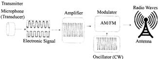
Microphone
It converts sound waves into electrical waves. When a sound is made, the varying air pressure on the microphone generates an audio electric signal corresponding to the frequency of the original signal.
Audio Amplifier
The weak audio signals from the microphone are made strong by amplification through cascaded audio amplifiers. The output signal is fed to the modulator for modulation.
Oscillator
Oscillator produces a high frequency signal called a carrier wave. Usually, crystal oscillators are used. Radio frequency amplifier stages raise the power level of the carrier wave to a sufficient level (generally to several kilowatts), the high power helps in transmitting the signal to long distances.
Modulator
The modulator receives the amplified audio signals and carrier wave so formed in the previous stages. Here, the audio signal is superimposed on the carrier wave in a suitable manner. Result wave is called modulated wave or radio wave and the process is called modulation, the process of modulation permits the transmission of audio signal at the carrier frequency. As the can frequency is very high, therefore the audio signal can transmitted to large distances, the radio waves from the transmitter are fed into the transmitting antenna from where these are radix into space.
2) TRANSMISSION OF RADIO WAVES
The radio waves are radiated in all directions by the transmitting antenna. These radio waves travel with the velocity of light i.e., 3* 108 m/sec. The radio waves are electromagnetic waves posses the same general properties. These are similar to light and a wave except that they have longer wavelength. It is clear d radio waves are sent without employing any wire. It can be easily shown that at high frequency, electrical energy can be radiated into space.
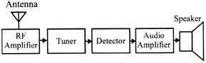
3) RADIO RECEIVER
A radio receiver is the opposite of a radio transmitter. It uses antenna to capture radio waves, processes those waves to extract only those waves that are vibrating at the desired frequency, tracts the audio signals that were added to those waves, amplifies the audio signals, and finally plays them on a speaker. when the radio waves reach the receiving antenna it induces emf in it which is very small in magnitude and is fed to the radio receiver Here, the radio waves are first amplified then the process of demodulation to extracts signal from them. the signal is amplified by audio amplifiers and then fed to the speaker for reproduction into sound waves.
RADAR
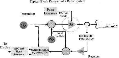
Radar is an electromagnetic system for the detection and location of objects (Radio Detection and Ranging). Radar operates by transmitting a particular type of waveform and detecting the nature of the signals reflected back from objects. Radar can't resolve detail or color as well as the human eye (an optical frequency passive scatter meter).
Radar can see in conditions which do not permit the eye to see such as darkness, haze, rain, smoke.
Radar can also measure the distances to objects. The elemental radar system consists of a transmitter unit, an antenna for emitting electromagnetic radiation and receiving the echo, an Energy detecting receiver and a processor.
A portion of the transmitted signal is intercepted by a reflecting object (target) and is reradiated in all directions. The antenna collects the returned energy in the backscatter direction and delivers it to the receiver. The distance to the receiver is determined by measuring the time taken for the electromagnetic signal to travel to the target and back.
The direction of the target is determined by the angle of arrival (AOA) of the reflected signal. Also if there is relative motion between the radar and the target, there is a shift in frequency of the reflected signal (Doppler Effect) which is a measure of the radial component of the relative velocity. This can be used to distinguish between moving targets and stationary ones.
Radar was first developed to warn of the approach of hostile aircraft and for directing anti-aircraft weapons. Modem radars can provide AOA, Doppler, and MTI etc.
Radar Antenna
Antenna is a structure which serves as a transition between wave propagating in free space, and the fluctuating voltages in the circuit to which it is connected. An antenna either receives energy from an electromagnetic field or radiates electromagnetic waves produced by a high frequency generator. This section deals specifically with antenna used in radar installations.
An antenna is a device that acts as a transformer to provide a good match between the feeding line as a local source of power and free space. If the antenna is not matched to free space, power will be reflected back toward the transmitter, resulting in a loss in radiated power. The antenna is one of the most critical parts of a radar system. It performs the following essential functions:
RADAR EQUATION
The power\[{{P}_{r}}\]returning to the receiving antenna is given by the equation:
\[{{P}_{r}}=\frac{{{p}_{t}}{{G}_{t}}{{A}_{r}}\sigma {{F}^{4}}}{{{(4\pi )}^{2}}R_{t}^{2}R_{R}^{2}}\]
Where
In the common case where the transmitter and the receiver are at the same location, \[{{R}_{t}}={{R}_{r}}\]and the term can be replaced by\[{{R}^{4}}\], where R is the range. These yields:
\[{{P}_{r}}=\frac{{{P}_{t}}{{G}_{t}}{{A}_{r}}\sigma {{F}^{4}}}{{{(4\pi )}^{2}}{{R}^{2}}}\]
This shows that the received power declines as the fourth power of the range, which means that the received power from distant targets is relatively very small.
Additional filtering and pulse integration modifies the radar equation slightly for pulse-Doppler radar performance, which can be used to increase detection range and reduce transmit power.
The equation above with F=1is a simplification for transmission in a vacuum without interference. The propagation factor accounts for the effects of multipath and shadowing and depends on the details of the environment. In a real-world situation, path loss effects should also be considered.
SUBMARINE TELYGRAPHY
A submarine communications cable is a cable laid on the sea bed between land-based stations to carry telecommunication signals across stretches of ocean. The first submarine communications cables, laid in the 1850s, carried telegraphy traffic. Subsequent generations of cables carried telephone traffic, then data communications traffic. Modern cables use optical fibe" technology to carry digital data, which includes telephone, Interne and private data traffic.
Selecting Submarine Cable Routes
Cable routes are surveyed to avoid great depths and one popular area in the North Atlantic became known as "Telegraph Plateau'.
Areas of volcanic activity are also best avoided, however, in 192'S an eruption and associated underwater landslide caused breakages in over 20 telegraph cables with repairs taking over two months- Cable laying ships show at the masthead a double cone between two balls to indicate they are cable laying and require a clear passage. It is a complicated task with the rate of paying out continually adjusted to match the slope of the ocean bed. Despite showing cables on Admiralty charts, dragged anchors can damage cables and expensive, time consuming location and repairs needed. Today a fleet of modern cable laying ships, equipped with the latest dynamic positioning, computerized profiling and thrusters, remains on standby at strategic locations throughout the world to locate and repair faulty or damaged submarine cables.
Satellite
A satellite is a moon, planet or machine that orbits a planet or six-H For example, Earth is a satellite because it orbits the sun. Likewise the moon is a satellite because it orbits Earth, Usually, the word "satellite" refers to a machine that is launched into space and moves around Earth or another body in space.
Earth and the moon are examples of natural satellites Thousands of artificial, or man-made, satellites orbit Earth. Take pictures of the planet that help meteorologists predict weather and track hurricanes. Some take pictures of other planets, the sun, black holes, dark matter or faraway galaxies. These pictures help scientists better understand the solar system and universe.
Still other satellites are used mainly for communications, such as beaming TV signals and phone calls around the world. A group of more than 20 satellites make up the Global Positioning System, or GPS. If you have a GPS receiver, these satellites can help help figure out your exact location.
Sputnik 1 was the first satellite in space. The Soviet Union launched it in 1957.
Important of Satellites
The bird's-eye view that satellites have allows them to see large areas of Earth at one time. This ability means satellites can collect more data, more quickly, than instruments on the ground.
Satellites also can see into space better than telescopes Earth's surface. That's because satellites fly above the clouds, dust and molecules in the atmosphere that can block the view from ground level.
Before satellites, TV signals didn't go very far. TV signals only travel in straight lines. So they would quickly trail off into space instead of following Earth's curve. Sometimes mountains or tall buildings would block them. Phone calls to faraway places were also a problem. Setting up telephone wires over long distances or underwater is difficult and costs a lot.
With satellites, TV signals and phone calls are sent upward to a satellite. Then, almost instantly, the satellite can send them back down to different locations on Earth.
Parts of a Satellite
Satellites come in many shapes and sizes. But most have at least two parts in common - an antenna and a power source. The antenna sends and receives information, often to and from Earth.
The power source can be a solar panel or battery. Solar panels make power by turning sunlight into electricity.
Many NASA satellites carry cameras and scientific sensors.
Sometimes these instruments point toward Earth to gather
Information about its land, air and water. Other times they face toward space to collect data from the solar system and universe.
Satellites Orbit Earth
Most satellite are launched into space on rockets. A satellite orbits Earth when its speed is balanced by the pull of Earth's gravity without this balance, the satellite would fly in a straight line off into space or fall back to Earth. Satellites orbit Earth at different heights, different speeds and along different paths. The two most common types of orbit are "geostationary and "polar."
A geostationary0 satellite travels from west to east over the equator.
It moves in the same direction and at the same rate Earth is spinning.
From Earth, a geostationary satellite looks like it is standing still since it is always above the same location.
Polar-orbiting satellites travel in a north-south direction from pole to pole. As Earth spins underneath, these satellites can scan the entire globe, one strip at a time.
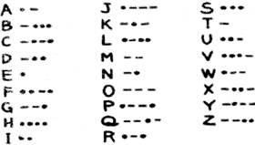
MORSE CODE
Morse code is a system of communication developed by Samuel F.B. Morse that uses a series of dots and dashes to relay coded messages. Though it was originally devised as a way of communicating over telegraph lines. Morse Code is still used today by amateur radio enthusiasts and is also useful for sending urgent distress signals in emergency situations. While learning Morse Code isn't particularly difficult, it does require study and dedication like any other language.
Morse
Code is comprised of two different signal units-dots and dashes. Dots look like simple periods, whereas dashes are long horizontal lines similar to hyphens. Every character in the English language can be represented using these two signals.


You need to login to perform this action.
You will be redirected in
3 sec

