Electrical Machine
Category : Railways
Electrical Machine
SINGLE PHASE TRANSFORMER
EMF Equation of a Transformer
\[{{E}_{1}}=4.44f{{\phi }_{m}}{{N}_{1}},\]
where,\[{{E}_{1}}\]= RMS value of induced emf in primary winding
f= frequency
\[{{\phi }_{m}}\]= maximum flux in core
\[{{N}_{1}}\]= number of turns in primary winding.
Similarly, \[{{E}_{2}}=4.44f{{\phi }_{m}}{{N}_{2}},\]
where,\[{{E}_{2}}\]= RMS value of induced emf in secondary winding
\[{{N}_{2}}\]= Number of turns in secondary winding
Thus,
\[\frac{{{E}_{2}}}{{{E}_{1}}}=\frac{{{N}_{2}}}{{{N}_{1}}}=\frac{{{V}_{2}}}{{{V}_{1}}}=\frac{{{I}_{1}}}{{{I}_{2}}}=K\]
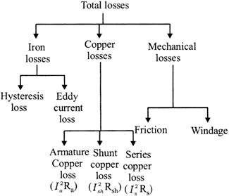
Losses in Transformer
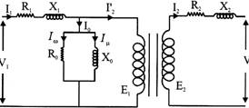
Equivalent Circuit
Equivalent Circuit of transformer is showing in fig.
Let
\[{{I}_{1}}\]\[=\]primary current
\[{{R}_{1}}\]\[=\]primary resistance
\[{{X}_{1}}\]\[=\]primary leakage reactance
\[{{I}_{0}}\]\[=\]no load current
\[{{I}_{2}}\]\[=\]secondary current transferred to primary
\[{{I}_{W}}\]\[=\]watt full component of no load current
\[{{I}_{\mu }}\]\[=\]magnetizing component of no load current
\[{{R}_{0}}\]\[=\]core loss resistance
\[{{X}_{0}}\]\[=\]magnetizing reactance
\[{{E}_{1}}\]\[=\]RMS value of induced emf in primary winding
\[{{E}_{2}}\]\[=\]RMS value of induced emf in secondary winding
\[{{R}_{1}}\]\[=\]secondary resistance
\[{{X}_{2}}\]\[=\]secondary leakage reactance
Phaser diagram
From the equivalent circuit of transformer, it can concluded that
\[{{E}_{2}}={{V}_{2}}+{{I}_{2}}{{R}_{2}}+{{I}_{2}}{{X}_{2}}\]
\[{{I}_{1}}={{I}_{0}}+{{I}_{2}}'\]
\[{{I}_{0}}={{I}_{W}}+{{I}_{\mu }}\]
\[{{V}_{1}}={{E}_{1}}+{{I}_{1}}{{R}_{1}}+{{I}_{1}}{{X}_{1}}\]
Phaser diagram is showing in fig.
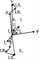
Fig. Phaser diagram
THREE PHASE TRANSFORMER
A three phase transformer or\[3-\phi \]transformer can be constructed either by connecting together three single-phase transformers, thereby forming a so-called three phase transformer bank or b) using one pre-assembled and balanced three phase transformers which consists of three pairs of single phase windings mounted onto one single laminated core.
In the case of three phase transformer windings, three forms of connection are possible: "star" (wye), "delta" (mesh) and "interconnected-star" (zig-zag). The combinations of the three windings may be with the primary delta-connected and the secondary star-connected, or star-delta, star-star or delta-delta, depending on the transformers use as shown in fig. When transformers are used to provide three or more phases they are generally referred to as a Polyphase Transformer.
|
Primary configuration |
Secondary configuration |
|
Delta (mesh) |
Delta (mesh) |
|
Delta (mesh) |
Star (wye) |
|
Star (wye) |
Delta (mesh) |
|
Star (wye) |
Star (wye) |
|
Interconnected Star |
Delta (mesh) |
|
Interconnected Star |
Star (wye) |
Three-phase Line Voltage and Current
|
Connection |
Phase Voltage |
Line Voltage |
Phase Current |
Line Current |
|
Star |
\[{{V}_{p}}={{V}_{L}}\div \sqrt{3}\] |
\[{{V}_{L}}=\sqrt{3}\times {{V}_{P}}\] |
\[{{I}_{P}}={{I}_{L}}\] |
\[{{I}_{L}}={{I}_{P}}\] |
|
Delta |
\[{{V}_{P}}={{V}_{L}}\] |
\[{{V}_{L}}={{V}_{P}}\] |
\[{{I}_{P}}={{I}_{L}}\div \sqrt{3}\] |
\[{{I}_{L}}=\sqrt{3}\times {{I}_{P}}\] |
|
Primary-secondary configuration |
Line voltage |
Line current |
|
Delta - delta |
\[{{V}_{L}}\Rightarrow n{{V}_{L}}\] |
\[{{I}_{L}}\Rightarrow \frac{{{I}_{L}}}{n}\] |
|
Delta - star |
\[{{V}_{L}}\Rightarrow \sqrt{3}.n{{V}_{L}}\] |
\[{{I}_{L}}\Rightarrow \frac{{{I}_{L}}}{\sqrt{3}.n}\] |
|
Star - delta |
\[{{V}_{L}}\Rightarrow \frac{n{{V}_{L}}}{\sqrt{3}}\] |
\[{{I}_{L}}\Rightarrow \sqrt{3}.\frac{{{I}_{L}}}{n}\] |
|
Star - star |
\[{{V}_{L}}\Rightarrow n{{V}_{L}}\] |
\[{{I}_{L}}\Rightarrow \frac{{{I}_{L}}}{n}\] |
Where n equals the transformers "turns ratio" (T.R.) of the number of secondary windings \[{{N}_{S}}\]divided by the number of primary windings \[{{N}_{P}}.({{N}_{S}}/{{N}_{P}})\]
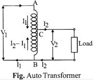
AUTO/TRANSFORMER
\[\frac{{{V}_{2}}}{{{V}_{1}}}=\frac{{{N}_{2}}}{{{N}_{1}}}=\text{constant=k}\]
\[\frac{\text{weight}\,\,\text{of}\,\,\text{auto}\,\,\text{transformer}}{\text{weight}\,\,\text{of}\,\,\text{two}\,\,\text{winding}\,\,\text{transformer}}=1-k\]
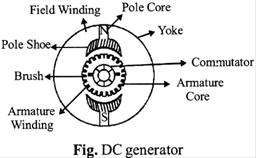
DC GENERATOR
Parts of DC generator
There are so many parts of DC generator such as:
(a) Yoke: It is made up of cast iron; it performs two main functions:
(1) It provides mechanical support for the poles.
(2) It carries the magnetic flux.
(b) Pole cores: These are made of solid pieces made out of either cast iron or cast steel.
(c) Pole shoes: These provide a uniform distribution of flux and support to the field winding.
(d) Armature core: It contains the armature conductor or coils. A core provides a very low reluctance path through the armature from N-S pole. It is cylindrical or drum shaped.
(e) Armature conductor: The armature winding is wound in the form of a flat rectangular coil.
(f) Commutator: The main function of a commutator is to facilitate the collection of current from the armature conductor.
Brushes: Brushes are there to collect current from the commutator. They are made up of carbon or graphite.
EMF Equation of a DC Generator
\[{{E}_{g}}=\frac{\phi ZN}{60}\times \frac{P}{A}volt\]
P = No of generator poles
Z = Total number of conductors = (Number of slots\[\times \]conductor/slots
N = Armature rotation in r. p. m.
\[\phi \]= flux /pole in weber
A = Number of conductors
(1) In case of lap winding \[A=P,\frac{\phi ZN}{60}Volts\]
(2) In case of wave winding \[A=2,\,\,{{E}_{g}}=\frac{\phi ZNP}{120}volts\]
Types of Generator
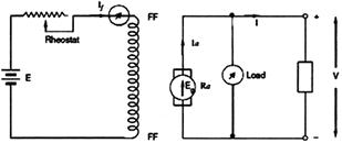
In separately excited DC generators as shown in fig. the open circuit characteristic or magnetizing characteristic is obtained by driving the machine at normal speed and varying the exciting current in steps from zero to maximum.
The excitation current is entirely independent of the load current in the armature.
Power Input \[={{E}_{g}}{{I}_{a}}\]
Power Output \[=V.{{I}_{a}}\]
(a) Series wound
(b) Shunt wound
(c) Compound wound
(i) Long shunt compound
(ii) Short shunt compound
To build up the voltage in self excited DC generators, following conditions should be met:
(i) Presence of residual magnetism in pole curve, and
(ii) Forward direction of rotation.
When the armature of a self excited DC generator rotates at rated speed, the voltage across terminals increases up to rated voltage. Initially, due to residual magnetism there is a small flux which induces small residual voltage, which increases the field current. Finally, terminal voltage reaches the rated value.
(c) DC Compound Generator: In compound generators the - field winding is connected in series as well as parallel to the armature circuit.
In long shunt generators shown in fig. the shunt winding is connected across armature and series field but in short shunt it covers only armature winding shown in fig. If the flux produced by series and shunt windings is additive, the dc generator is known as cumulative compound generator and if fluxes are deductive then it is known as differential compound generator.
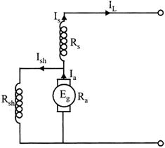
Fig. Short shunt DC generator
Types of winding
There are two types of windings:
(1) Lap winding
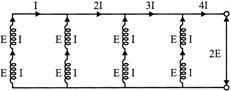
Fig. Lap winding
A = P, where A = Number of parallel paths,
P = Number of poles
(2) Wave winding
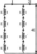
Fig. Wave winding
POWER LOSSES
\[Hysteresis\,\,loss\,\,{{p}_{n}}=n{{({{B}_{\max }})}^{X}}f\,\,V\,\,watts\]
Mechanical Efficiency
\[{{\eta }_{m}}=\frac{{{E}_{g}}{{I}_{a}}}{{{E}_{g}}{{I}_{a}}+straylosses}\]
Electrical Efficiency
\[{{\eta }_{m}}=\frac{{{V}_{l}}}{{{E}_{g}}{{I}_{a}}}\]
Commercial or Overall Efficiency
\[{{\eta }_{c}}={{\eta }_{m}}{{\eta }_{e}}\]
DC MOTOR
IT is an electrical motor which converts electrical energy to mechanical energy.
Types of DC Motors
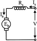
(1) Series Wound Motor
\[{{I}_{a}}={{I}_{s}}\]
\[V={{E}_{b}}+{{I}_{a}}{{R}_{a}}+{{I}_{s}}{{R}_{s}}\]
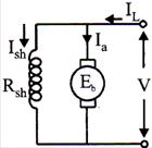
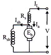
(2) Shunt Wound Motor
\[{{I}_{L}}={{I}_{a}}+{{I}_{sh}}\]
\[{{I}_{a}}={{I}_{L}}-{{I}_{sh}}\]
\[V={{E}_{b}}+{{I}_{a}}{{R}_{a}}\]
\[{{I}_{sh}}=\frac{V}{{{R}_{sh}}}\]
Note:
Case (1) – If the speed increases,\[{{E}_{b}}\]also increases and hence \[V-{{E}_{b}}\]decreases. Thus, armature current \[{{I}_{a}}\]decreases.
Case (2) – If the speed is less, then \[{{E}_{b}}\]is also less and hence more current flows which develops a motor torque.
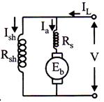
(3) Long shunt compound wound Motor
\[{{I}_{L}}={{I}_{a}}+{{I}_{sh}}\]
\[{{I}_{a}}={{I}_{L}}-{{I}_{sh}}\]
\[{{I}_{sh}}=\frac{V}{{{R}_{sh}}}\]
\[V={{E}_{b}}+{{I}_{a}}({{R}_{a}}+{{R}_{s}})\]
(4) Short shunt compound wound Motor
\[{{I}_{L}}={{I}_{a}}+{{I}_{sh}}\]
\[V={{E}_{b}}+{{I}_{a}}({{R}_{a}}+{{R}_{s}})\]
\[{{I}_{sh}}=\frac{V-{{I}_{L}}{{R}_{s}}}{{{R}_{sh}}}\]
\[{{I}_{sh}}=\frac{{{E}_{b}}+{{I}_{a}}{{R}_{a}}}{{{R}_{sh}}}\]
Starting of DC Motor
When the armature of a DC motor is at standstill, the back emf is zero as \[N=0\,\,\left( \because \,\,{{E}_{b}}=\frac{p\phi ZN}{60A} \right)\]If a DC motor is connected erectly to the supply then a heavy current will flow through armature conductors\[\left( \because \,\,\,{{I}_{a}}=\frac{V-{{E}_{b}}}{{{R}_{a}}} \right)\]because\[{{R}_{a}}\] is very small
(i.e. less than\[1\Omega \]). This heavy current may damage the armature windings. Thus, for the protection of the motor against the flow of large current during starting period starters are used.
THREE PHASE INDUCTION MOTORS
Principle
In AC motors, the rotor does not receive electric power by conduction, but by induction in exactly the same way as the secondary of a \[2-\]winding transformer receives its power from the primary. That is why, such motors are known as induction motors. In fact, an induction motor can be treated as a rotating transformer, i.e. one in which the primary winding is stationary but the secondary is free to rotate.
Construction of Induction Motor
An induction motor essentially consists of two main parts:
(A) Stator (B) Rotor
(a) Squirrel – cage rotor – Motors employing this type of rotors are known as the squirrel-cage induction motors.
(b) Phase wound or Wound rotor - Motors employing these types of rotors are variously known as phase -wound motor or wound motor or as slip-ring motors.
Slip
The difference between the synchronous speed \[{{N}_{s}}\]and me actual speed, N of the rotor is known as the slip.
\[%\,slip\,=\frac{{{N}_{s}}-N}{{{N}_{s}}}\times 100\]
(i) \[{{N}_{s}}-N\] is called the slip speed
(ii) Rotor speed N =\[{{N}_{s}}(1-s)\]
(iii) At the start, slip is 100% or 1.
(iv) In an induction motor, the change in slip from no-load to full load is hardly 0.1%to 3% so that it is essentially constant speed motor.
Frequency of Rotor Current
The frequency of a voltage or current induced due to the relative speed between a vending and a magnetic field is given by the general formula
\[Frequency=\frac{Np}{120}\]
Where N = Relative speed between magnetic field and the winding
p = Number of poles
Rotor current at a slip, \[{{I}_{2}}=\frac{s\,\,{{E}_{2}}}{\sqrt{R_{2}^{2}+(sX_{2}^{2})}}\]
Torque and Torque-Slip Characteristics-
Torque
The torque developed by the rotor is proportional to the product of rotor current and fundamental magnetic flux cutting the rotor.
The total torque
\[T=K\phi {{I}_{2}}\cos {{\phi }_{2}}.\]
where\[{{\phi }_{2}}\]is the useful fundamental flux per pole and is proportional to rotor emf (max.)
SO, \[T=K{{E}_{2}}{{I}_{2}}\cos {{\phi }_{2}}\]
We know \[{{I}_{2}}=\frac{s{{E}_{2}}}{\sqrt{R_{2}^{2}+{{s}^{2}}X_{2}^{2}}}\,\,\,and\,\,\cos \,{{\phi }_{2}}=\frac{R}{\sqrt{R_{2}^{2}+{{s}^{2}}X_{2}^{2}}}\]
So \[T=\frac{K\,s\,E_{2}^{2}\,{{R}_{2}}}{R_{2}^{2}+{{s}^{2}}X_{2}^{2}}\]
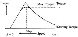
Fig. Torque Slip Characteristics
For slip, s=1, i.e. standstill the torque\[T=\frac{K\,{{R}_{2}}\,E_{2}^{2}}{R_{2}^{2}+X_{2}^{2}}\] is constant and is known as starting torque. The approximate torque slip curve is shown in fig. The region where \[\frac{dT}{ds}>0\]is called stable region of operation where the motor normally operates.
Starting Torque
Torque, T=\[\frac{KsE_{2}^{2}{{R}_{2}}}{R_{2}^{2}+{{(s{{X}_{2}})}^{2}}}\]
At the time of starting, s = 1 and \[{{E}_{2}}\] is constant then
\[{{T}_{st}}=\frac{{{K}_{1}}{{R}_{2}}}{R_{2}^{2}+X_{2}^{2}}\]
Maximum torque occurs when rotor resistance is equal to rotor reactance and the relation between starting torque and rotor resistance becomes
\[{{T}_{ST}}=\frac{{{K}_{1}}}{2{{R}_{2}}}\]
SINGLE-PHASE INDUCTION MOTORS
In a single-phase motor it has only a single field winding excited with alternating current; therefore, it does not have a revolving field like three-phase motors. Thus, it does not self-starting.
Synchronous Speed
As in the case of three-phase motors, the synchronous speed of all single-phase induction motors is given by the equation
\[{{n}_{s}}=\frac{120f}{p}\]
Where \[{{n}_{s}}\]= synchronous speed [rpm]
f= frequency of the source [Hz]
p = number of poles
Starting Torque for Single Phase I.M
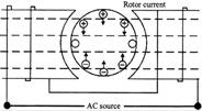
Fig. Currents in the rotor bars when the rotor is locked
Torque-Speed Characteristic
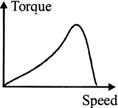
Fig. Torque speed curve
SYNCHRONOUS MACHINES
A synchronous machine is an a.c. machine in which the rotor moves at a speed, which bears a constant relationship to the frequency of the current in the armature winding as shown in fi As a motor, the shaft speed must remain constant irrespective the load, provided that the supply frequency remains constant
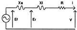
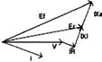
Fig. Equivalent circuit of the generator synchronous machine Equivalent Impedance
\[{{Z}_{s}}=\sqrt{\left( {{R}^{2}}+X_{s}^{2} \right)}\]
Voltage Regulation
The voltage regulation of an alternator is normally defined as the rise in terminal voltage when a given load is thrown off. Thus. if Ef the induced voltage on open-circuit and V is the terminal voltage at a given load, the voltage regulation is given by-
Per unit regulation\[=\frac{Ef-V}{V}\]


You need to login to perform this action.
You will be redirected in
3 sec

