Communication System
Category : Railways
Communication System
MODULATION
The process of impressing low-frequency information to be transmitted on to a high-frequency wave, called the carrier wave, by changing the characteristics of either its amplitude, frequency, or phase angle is called modulation. The main function of the carrier wave is to carry the audio or video signal from the transmitter to the receiver. The wave that is resulted due to superimposition of audio signal and carrier wave is called the modulated wave.
Types of Modulation
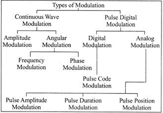
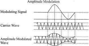
AMPLITUDE MODULATION (AM)
The method of varying amplitude of a high frequency carrier wave in accordance with the information to be transmitted, keeping the frequency and phase of the carrier wave unchanged is called Amplitude Modulation. The information is considered as the modulating signal and it is superimposed on the carrier wave by applying both of them to the modulator. The detailed diagram showing the amplitude modulation process is given below.
Modulation Index (m)
The ratio between the amplitude change of carrier wave to the amplitude of the normal carrier wave is called modulation index-
It is represented by the letter 'm'.
It can also be defined as the range in which the amplitude of the carrier wave is varied by the modulating signal.
\[m={{V}_{m}}/{{V}_{c}}\]
Percentage modulation, \[%\,\,m={{m}^{*}}100={{V}_{m}}/{{V}_{c}}*100\]
The percentage modulation lies between 0 and 80%.
Power Relations in an AM wave
A modulated wave has more power than had by the carrier wave before modulating. The total power components in amplitude modulation can be written as:
\[{{P}_{total}}={{P}_{carrier}}+{{P}_{LSB}}+{{P}_{USB}}\]
Considering additional resistance like antenna resistance R.
\[{{P}_{carrier}}={{[({{V}_{c}}/\sqrt{2})/R]}^{2}}={{V}^{2}}_{C}/2R\]
ANGLE MODULATION
In the angle modulation, again there are two different types of modulations.
Frequency modulation.
Phase modulation.
To generate a frequency modulated signal, the frequency of the radio carrier is changed in line with the amplitude of the incoming audio signal.
When the audio signal is modulated onto the radio frequency carrier, the new radio frequency signal moves up and down in frequency. The amount by which the signal moves up and down is important. It is known as the deviation and is normally quoted as the number of kilo hertz deviation. As an example the signal may have a deviation of plus and minus 3 kHz, i.e. \[\pm \,\,3\,\,kHz.\]In this case the carrier is made to move up and down by 3 kHz.
Broadcast stations in the VHF portion of the frequency spectrum between 88.5 and 108 MHz use large values of deviation. typically \[\pm \,\,75\,\,kHz.\] This is known as wide-band FM (WBFM). These signals are capable of supporting high quality transmissions, but occupy a large amount of bandwidth. Usually 200 kHz is allowed for each wide-band FM transmission. For communications purposes less bandwidth is used. Narrow band FM (NBFM) often uses deviation figures of around \[\pm \,\,3\,\,kHz.\]It is narrow band FM that is typically used for two-way radio communication applications. Having a narrower band it is not able to provide the high quality of the wideband transmissions, but this is not needed for applications such as mobile radio communication.
In the phase modulation, we vary the carrier signal in accordance with the phase of the modulating signal or message signal by keeping the frequency constant. If the amplitude of message or modulating signal is huge then the phase shift will also be greater.
Advantages and Disadvantages of Phase Modulation:
Applications of Phase Modulation:
PULSE DIGITAL MODULATION
When we take the pulse digital modulation, we use a periodic sequence of rectangular pulses as the carrier signal. Pulse digital modulation is also used in both analog and digital communications
Types of Modulation:
In pulse width modulation, there are different types of modulation for analog and digital as shown below:
COMMUNICATION SYSTEM
Communication is the process of establishing connection or link between two points for information exchange. (OR)
Communication is simply the basic process of exchanging information.
The electronics equipements which are used for communication purpose, are called communication equipments. Different communication equipments when assembled together form a communication system.
Typical example of communication system are line telephony and line telegraphy, radio telephony and radio telegraphy, radio broadcasting, point-to-point communication and mobile communication, computer communication, radar communication, television broadcasting, radio telemetry, radio aids to navigation, radio aids to aircraft landing etc.
The Communication Process
In the most fundamental sense, communication involves me transmission of information from one point to another through a succession of process as listed below:
Block Diagram of Communication System
Figure shows the block diagram of a general communication system, in which the different functional elements are represented by blocks.
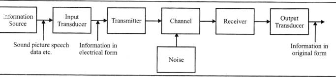
The essential components of a communication system are information source, input transducer, transmitter, communication channel, receiver and destination.
Now, we shall discuss the functioning of these blocks.
(i) Information Source
As we know, a communication system serves to communicate a message or information. This information originates in the "formation source.
In general, there can be various messages in the form of words, group of words, code, symbols, sound signal etc. However, out of these messages, only the desired message is selected and communicated.
Therefore, we can say that the function of information source is to produce required message which has to be transmitted.
(ii) Input Transducer
A transducer is a device which converts one form of energy into another form.
The message from the information source may or may not be electrical in nature. In a case when the message produced by the information source is not electrical in nature, an input transducer
is used to convert it into a time- varying electrical signal for example, in case of radio- broadcasting, a microphone converts the information or massage which is in the form of sound waves into corresponding electrical signal
(iii) Transmitter
The function of the transmitter is to process the electrical signal from different aspects.
For example in radio broadcasting the electrical signal obtained from sound signal, is processed to restrict its range of audio frequencies (upto 5 kHz in amplitude modulation radio broadcast) and is often amplified.
In wire telephony, no real processing is needed. However, in long-distance radio communication, signal amplification is necessary before modulation.
Modulation is the main function of the transmitter. In modulation, the message signal is superimposed upon the high-frequency carrier signal.
In short, we can say that inside the transmitter, signal processings such as restriction of range of audio frequencies, amplification and modulation of are achieved. All these processings of the message signal are done just to ease the transmission of the signal through the channel.
(iv) The Channel and The Noise
The term channel means the medium through which the message travels from the transmitter to the receiver. In other words, we can say that the function of the channel is to provide a physical connection between the transmitter and the receiver.
There are two types of channels, namely point-to-point channels and broadcast channels.
Example of point-to-point channels are wire lines, microwave links and optical fibres. Wire-lines operate by guided electromagnetic waves and they are used for local telephone transmission.
Noise is an unwanted signal which tend to interfere with the required signal. Noise signal is always random in character. Noise may interfere with signal at any point in a communication system. However, the noise has its greatest effect on the signal in the channel.
(v) Receiver
The main function of the receiver is to reproduce the message signal in electrical form from the distorted received signal. This reproduction of the original signal is accomplished by a process known as the demodulation or detection. Demodulation is the reverse process of modulation carried out in transmitter.
(vi) Destination
Destination is the final stage which is used to convert an electrical message signal into its original form.
For example in radio broadcasting, the destination is loudspeaker which works as a transducer i.e. converts electrical signal in the form of original sound signal.
TELEVISION
Television (TV) is a telecommunication medium used transmitting moving images in monochrome (black and white) or in color, and in two or three dimensions and sound. The term can refer to a television set, a television program ("TV show’’) or the medium of television transmission. Television is a mass medium for entertainment, education, news, politics, gossip, and advertising
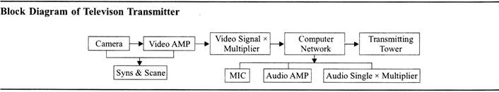
A Television Transmitter
A television transmitter is a device which broadcasts an electromagnetic signal to the television receivers. Televisual transmitters may be analog or digital.
The principals of primarily analog systems are summarized as they are typically more complex than digital transmitters due the multiplexing of VSB and FM modulation stages
Color Television Fundamentals
To better understand how to select good colors and color combinations for web pages or other computer graphics work, it is essential to understand a few concepts about color television, which is the basis of computer video systems. Many techniques and optimizations were developed for color television to conserve bandwidth, and these techniques were developed based on research into how the human eye perceives light, detail and color.
This information still largely applies to computer video displays, and absolutely applies if computer video is to be transmitted or stored in any color television video format.
TELEVISION ANTENNA
A television antenna, or TV aerial, is an antenna specifica3lB designed for the reception of over-the-air broadcast television signals, which are transmitted at frequencies from about 41 to 250 MHz in the VHF band, and 470 to 960 MHz in the UHF in different countries. Television antennas are manufacture two different types: "indoor" antennas, to be located on top or next to the television set, and "outdoor" antennas, mounted on a mast on top of the owner's house. They can also be mounted in a loft or attic, where the dry conditions and increased elevation are advantageous for reception and antenna longevity. Outdoor antennas are more expensive and difficult to install, but are necessary for adequate reception in fringe areas far from television stations. The most common types of indoor antennas are the dipole ("rabbit ears") and loop antennas, and for outdoor antennas the yagi, log periodic, and for UHF channels the multibay reflective array antenna.
ANTENNA FUNDAMENTALS
In radio an antenna is the interface between radio waves propagating through space and electric currents moving in metal conductors, used with a transmitter or receiver. In transmission, a radio transmitter supplies an electric current to the antenna's terminals and the antenna radiates the energy from the current as electromagnetic waves (radio waves). In reception, an antenna intercepts some of the power of an electromagnetic wave in order to produce0 an electric current at its terminals, that is applied to a receiver to be amplified. Antennas are essential components of radio equipment, and are used in radio broadcasting, broadcast television two-way radio, communications receivers, radar, cell phones, satellite communications and other devices.
Antenna Frequency
The efficiency of an antenna is a ratio of the power delivered to the antenna relative to the power radiated from the antenna. A high efficiency antenna has most of the power present at the antenna’s input radiated away. A low efficiency antenna has most of the power absorbed as losses within the antenna, or reflected away due to impedance mismatch.
Antenna Gain
The term Antenna Gain describes how much power is transmitted in the direction of peak radiation to that of an isotropic source. Antenna gain is more commonly quoted than directivity in an antenna’s specification sheet because it takes into account the actual losses that occur.
Radiation pattern
A radiation pattern defines the variation of the power radiated by an antenna as a function of the direction away from the antenna. This power variation as a function of the arrival angle is observed in the antenna's far field.
Antenna Bandwidth
Bandwidth is another fundamental antenna parameter. Bandwidth the range of frequencies over which the antenna can properly radiate or receive energy. Often, the desired bandwidth is of the determining parameters used to decide upon an antenna. For instance, many antenna types have very narrow bandwidths and cannot be used for wideband operation.
Antenna Efficiency
The efficiency of an antenna is a ratio of the power delivered to the antenna relative to the power radiated from the antenna. A high efficiency antenna has most of the power present at the antenna's input radiated away A low efficiency antenna has most of the power absorbed as losses within the antenna, or reflected away due to impedance mismatch.
Antenna Directivity
Directivity is a fundamental antenna parameter. It is a measure of how 'directional' an antenna's radiation pattern is. An antenna that radiates equally in all directions would have effectively zero directionality, and the directivity of this type of antenna would be 1 (or 0 dB).
TROUBLESHOOTING TV RECEPTION
Possible Causes
Once we have properly installed the antenna, changed the input on TV to 'ANTENNA', and run a channel scan, we should be receiving at least some of local channels. If this is not the case, the reason could be one of the following:
Antenna Temperature
It is a parameter that describes how much noise an antenna produces in a given environment. This temperature is not the physical temperature of the antenna. Moreover, an antenna does not have an intrinsic "antenna temperature" associated with it; rather the temperature depends on its gain pattern and the thermal environment that it is placed in. Antenna temperature is also sometimes referred to as Antenna Noise Temperature.
Type of TV Antennas
MICRO WAVE ENGINEERING
There are two groups of microwave devices.
Semiconductor Microwave Devices
There are the following microwave semi-conductor devices.
Backward Diode
It is one of the microwave semiconductor devices which are used as an oscillator and mixer. The backward diode is made of gallium arsenide semiconductor. This diode is used up to the frequencies of 200 GHz. The abbreviation of the backward diode is BWD. This diode works at low input power and it provides the high output power.
Gunn Diode
It is the microwave semiconductor diode which is used as an oscillator. In some of the cases Gunn diode can also be used as an amplifier. Its frequency range is from 4 GHz to 100 GHz.
The semiconductor material used for Gunn diode is gallium arsenide or indium phosphate mixed with the silicon.
![]()
Impatt Diode
The abbreviation of impatt diode is taken from word impact avalanche transit time. This diode is used for oscillation and amplificaiton of the microwave length of frequency.
The higher range of frequency of 200 GHz.
![]()
Schottky Diode
This diode is used for the rectification of microwave length of frequencies. In some of the cases we used the shocttky diode for switching and mixing purposes also. The frequency range of this diode is from 3 Mhz of 10 GHz.

Tunnel Diode
![]()
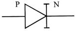
Varacter Diode
Varactor diode is mostly used in television and F. M receiver circuits. This doode can also be used in FM transmitter's circuits. The frequecy range of varactor diode is up to 105 GHz. This type of diode changes its capacitance with the change of the biasapplied to it.
![]()
Transistors
The coventional transistor cannot be used for the microwave frequencies because of its low efficiency and high distortion. The field effect transistors (FET) made of gallium arsenide semiconductor material is used for this purpose due to its efficient energy bands for very high frequency. We use these transistors for the purpose of amplification of the high frequencies.
Integrated Circuits (I.C)
As the inductance and capacitance for the very high frequencies is supposed to be very small, therefore the physical size of inductor and capacitor becomes the smallest possible at very high frequencies. So, the hybrid integrated circuits can be easily manufactured for the purpose of microwave frequencies.
WAVEGUIDE
Waveguide is the type of transmission line which carries microwave frequencies from source to load. The energy is in the form of electric field and magnetic field which are perpendicular to each other the electric field and magnetic field inside. The waveguide is also perpendicular to the direction of propagarioa as the energy is in the form of electric/magnetic field. Therefore,
it is handle the high power of micro wave length of frequencies.
Types of Wave guide:
There are the basic two types of the wave guide.
Construction:
Circular wave Guide:

As shown in the above diagram the circular waveguide is designed from a conducting pipe which is hollow from the center and polished from interior portion. The outer surface of the wave guide is coded with the insulated paint in order to avoid dust and rust. These types of wave guide are available in different lengths and sizes in order to fulfill the requirement of the circuit.
Rectangular Wave Guide

As shown in the above diagram, the rectangular wave guide a designed from conducting material in rectangular shape which is hollow from the center and fully polished from interior. The outer surface of the wave guide is coded with insulating material paint in order to avoid dust and rust. There types of wave guides are available in different lengths and sizes in order to fulfill the requirements of the circuit.
Flexible Waveguide
It is the type of waveguide which can be easily turn and twisted in circuits to connect the source with the load. This types of wave guide is designed in such a way that internal portion a made of conducting material in spring shape. The external portion is covered with the rubber to avoid dust, rust and humidity.
The flexible waveguide is used in such microwave equipment's where the path from load to the source is twisty.
Importance of Microwave Antennas in
Communication System
A system used for transferring the data between persons am equipments is called communication system. The system usually consists of individual networks, relay stations, transmission system, terminal equipment, interconnection cable and inter-operation performing as an integrated whole.
Anntenna plays a crucial role in this communication system, which is used to transmit and receive the data. The classification of the antenna is based on the specifications like frequency, porarization, radiation, etc.
The antenna that is operated at microwave frequency is knows as microwave antenna. There are different types of microwave antennas over a wide range of applications including home communication based applications.
Classification of Microwave Antennas
These antennas are also known as patch antennas. A micro strip patch antenna consists of a radiating patch that is bonded to a dielectric substrate on one side and has a ground plane on the other side.
The patch is generally composed of conducting materials like copper or gold. The operational frequency of these antennas range between 100 MHz and 100 GHz. Due to the advantages like less weight, low volume and low fabrication cost, these antennas can be manufactured in large quantities.
The micro strip patch antennas are well-known for their performance and extent of usage. The usage of micro strip antennas in the wide range could take over the usage of conventional antennas in applications.
There are several applications that use the micro-strip patch antennas, such as global positing satellites, cellular phones, personal and paging devices.
The Horn antenna or Microwave Horn is an antenna consisting of a waveguide whose end walls are flared outside to form a megaphone like structure, as shown in the below figure. These horns are widely used as antennas at ultra-high frequencies and microwave frequencies that are well above 300 MHz.
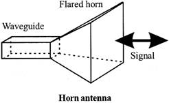
These are used to measure the gain of other antennas as calibrating antennas and directive antennas for devices like automatic door openers and microwave-radio meters.
The advantages of the horn antenna include moderate directivity, low-standing wave ratio and broad bandwidth. The gain of horn antenna ranges upto 25 db. These are extensively used at microwave frequency when the power gain needed is moderate.
A parabola antenna is an antenna that uses a parabolic reflector, a curved surface with cross sectional shape of a parabola to direct the radio waves. The shape of the antenna is in the form of a dish therefore, it is popularly known as dish antenna or parabolic dish. High directivity is the main advantage of the parabolic antenna.
These antennas find their applications as high gain antennas for point-to-point communication and also as radio telescopes. In addition to this, the parabolic antennas are also used as radar antennas because in radars there is a need for transmitting a narrow beam of radio waves to local objects like ships, airplanes, etc.
BLOCK DIAGRAM OF CRO (CATHODE RAY
OSCILLOSCOPE)
The figure below shows the block diagram of a general purpose CRO.
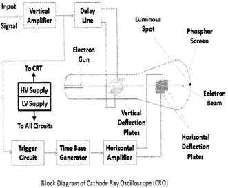
As we can see from the above figure above, a CRO employs a cathode ray tube (CRT) .which acts as the heart of the oscilloscope.
In an oscilloscope, the CRT generates the electron beam which are accelerated to a high velocity and brought to focus on a fluorescent screen. This screen produces a visible spot where the electron beam strikes it. By deflecting the beam over the screen in response to the electrical signal, the electrons can be made to act as an electrical pencil of light which produces a spot of light wherever it strikes.
For accomplishing these tasks various electrical signals and voltages are needed, which are provided by the power supply circuit of the oscilloscope.
Low voltage supply is required for the heater of the electron gun to generate the electron beam and high voltage is required for the cathode ray tube to accelerate the beam. Normal voltage supply is required for other control units of the oscilloscope.
Horizontal and vertical deflection plates are fitted between the electron gun and the screen so that these can deflect the beam according to the input signal.
To deflect the electron beam on the screen in horizontal direction i.e. X-axis with constant time dependent rate, a time base generator is provided in the oscilloscope.
The signal to be viewed is supplied to the vertical deflection plate through the vertical amplifier, so that it can amplify the signal to a level that will provide usable deflection of the electron beam.
As the electron beam is deflected in X-axis as well as Y-axis, a triggering circuit is provided for synchronizing these two types of deflections so that horizontal deflection starts at the same point of the input vertical signal each time it sweeps. Since CRT is the heart of the oscilloscope, now we are going to discuss its various components in detail.
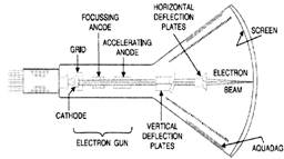
Cathode Ray Tube
The cathode ray tube or CRT is a vacuum tube of special geometrical shape which converts an electrical signal into a visual one. The figure below shows various parts of a cathode ray tube (CRT).
Now we will discuss each part of the CRT in detail.
(i) Glass Envelope
It is a conical highly evacuated glass housing which maintains vacuum inside it and supports various electrodes.
(ii) Electron Gun Assembly
The electron gun assembly consists of an indirectly heated cathode, a control grid, a focussing anode and an accelerating anode and it is used to produce a focused beam of electrons.
The control grid is held at negative potential w.r.t. cathode.
However, the two anodes are held at high positive potential w.r.t. cathode.
The cathode consists of a nickel cylinder coated with oxide coating and provides a large number of electrons.
The control grid encloses the cathode and consists metal cylinder with a tiny circular opening to keep electron beam small.
By controlling the positive potential on it, the focusing anode focuses the electron beam into a sharp pin point,
Due to the positive potential of about 10,000 V on accelerating anode which is much larger than on the focusing diode, the electron beam is accelerated to a high velocity In this way, the electron gun assembly forms a narrow, accelerated electron beam which produces a spot of light when it strikes the screen.
(iii) Deflection Plate Assembly
It consists of two sets of deflecting plates within the tube beyond the accelerating anode and is used for the deflection of the beam.
One set is called as vertical deflection plates and the other set is called horizontal deflection plates.
The vertical deflection plates are mounted horizontally in the tube. On application of proper potential to these plates, the electron beam can be made to move up and down vertically on the screen. The horizontal deflection plates are mounted vertically in the tube. On application of proper potential to these plates, the electron beam can be made to move right and left horizontally on the screen.
(iv) Screen
The screen is coated with some fluorescent materials such as zinc orthosilicate, zinc oxide etc and is the inside face of the tube.
When high velocity electron beam strikes the screen, a spot of light appears at the point of impact. The colour of the spot depends upon the nature of fluorescent material.


You need to login to perform this action.
You will be redirected in
3 sec

