Computer Network
A computer Network is a group of computer systems and other computing hardware devices that are linked together through communication channels to facilitate communication and resource-sharing among a wide range of users.
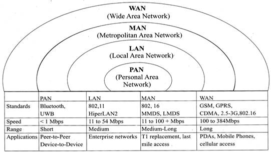
Generally, networks are distinguished based on their geographical span. A network can be as small as distance between your mobile phone and its Bluetooth headphone and as large as the Internet itself, covering the whole geographical world, i.e. the Earth.
TYPES OF COMPUTER NETWORKS
There are many types of Networks including:
- Personal Area Network (PAN): A Personal Area Network or simply PAN, is smallest network which is very personal to a user. This may include Bluetooth enabled devices or infra-red enabled devices. PAN has connectivity range up to 10 meters. PAN may include wireless computer keyboard and mouse, Bluetooth enabled headphones, wireless printers and TV remotes for examples.
- Local Area Network (LAN): A computer network spanned inside a building and operated under single administrative system is generally termed as Local Area Network. Usually, Local Area Network covers an organization such as offices, schools, college/universities etc. Number of systems may vary from as least as two to as much as 16 million LAN provides a useful way of sharing resources between end users. Resources like Printers, File Servers, Scanners and internet is easy sharable among computers. Local Area Networks are composed of inexpensive networking and routing equipment. It may contains local servers serving file storage and other locally shared applications. It mostly operates on private IP addresses and generally do not involve heavy routing. LAN uses either Ethernet or Token-ring technology. Ethernet is most widely employed LAN technology and uses Star topology while Token-ring is rarely seen. Data transfer rate in LAN is of the order 10 to 100 megabits per second (Mbps).
- Metropolitan Area Network (MAN): MAN, generally expands throughout a city such as cable TV network. It can be in form of Ethernet, Token-ring, ATM or FDDI. Metro Ethernet is a service which is provided by ISPs. This service enables its users to expand their Local Area Networks. For example, MAN can help an organization to connect all of its offices in a City. Backbone of MAN is high-capacity and high-speed fiber optics. MAN is works in between Local Area Network and Wide Area Network. MAN provides uplink for LANs to WANs or Internet.
- Wide Area Network (WAN): As name suggests, this network covers a wide area which may span across provinces and even a whole country. Generally, telecommunication networks are Wide Area Network. These networks provides connectivity to MANs and LANs. Equipped with very high speed backbone, WAN uses very expensive network equipment. WAN may use advanced technologies like Asynchronous Transfer. Mode (ATM), Frame Relay and SONET. WAN may be managed under by more than one administration.
- Virtual Private Network (VPN): VPN is a network that is constructed by using public wires usually the Internet to connect to a private network, such as a company>s internal network. There are a number of systems that enable you to create networks using the Internet as the medium for transporting data. These systems use encryption and other security mechanisms to ensure that only authorized users can access the network and that the data cannot be intercepted.
- Internetwork: A network of networks is called internetwork, or simply Internet. It is the largest network in existence on this planet. Internet hugely connects all WANs and it can have connection to LANs and Home networks. Internet uses TCP/IP protocol suite and uses IP as its addressing protocol. Present day, Internet is widely implemented using IPv4. Because of shortage of address spaces, it is gradually migrating from IPv4 to IPv6. Internet enables its users to share and access enormous amount of information worldwide. It uses www, ftp, email services, audio and video streaming etc. At huge level, internet works on Client- Server model. Internet uses very high speed backbone of fiber optics. To inter-connect various continents, fibers are laid under sea known to us as submarine communication cable. Internet is widely deployed on World Wide Web services using HTML linked pages and is accessible by some client software known as Web Browsers. When a user requests a page using some web browser located on some Web Server anywhere in the world, the Web Server responds with the proper HTML page. The communication delay is very low.
Internet is serving many proposes and is involved in many aspects of life. Some of them are:
- Web sites
- E-mail
- Instant Messaging
- Blogging
- Social Media
- Marketing
- Networking
- Resource Sharing
- Audio and Video Streaming
COMPARISON OF OSI REFERENCE MODEL AND TCP/IP REFERENCE MODEL
Following are some major difference between OSI Reference Model and TCP/IP Reference Model, with diagrammatic comparison below:
|
OSI (Open System Interconnection)
|
TCP/IP (Transmission Control Protocol/Internet Protocol)
|
|
1. OSI provides layer functioning and also defines functions of all the layers.
|
1. TCP/IP model is more based on protocols and protocols are not flexible with other layers.
|
|
2. In OSI model the transport layer guarantees the delivery of packets.
|
2. In TCP/IP model the transport layer does not guarantees delivery of packets.
|
|
3. Follows horizontal approach.
|
3. Follows vertical approach.
|
|
4.0SI model has a separate presentation layer.
|
4. TCP/IP does not have a separate presentation layer.
|
|
5. OSI is a general model.
|
5. TCP/IP model cannot be used in any other application.
|
|
6. Network layer of OSI model provide both connection oriented and connectionless service.
|
6. The Network layer in TCP/IP model provides connectioniness service.
|
|
7. OSI model has problem of fitting the protocols in the
|
7. TCP/IP model does not fit any protocol.
|
|
8. Protocols are hidden OSI model and are easily replaced as the technology changes.
|
8. In TCP/IP replacing protocol is not easy.
|
|
9. OSI model defines services, interfaces and protocols very clearly and makes clear distinction between them.
|
9. In TCP/IP it is not clearly separated its services. Interfaces and protocols.
|
|
10. It has 7 layers.
|
10. It has 4 layers.
|
ETHERNET
Ethernet is a Local Area Network implementation technology which is widely deployed.
Ethernet is network technology which shares media. Network which uses shared media has high probability of data collision. Ethernet uses CSMA/CD technology to detect collisions. CSMA/CD stands for Carrier Sense Multi Access/Collision Detection. When a collision happens in Ethernet, all its host rolls back and waits for some random amount of time and then re-transmit data. Ethernet connector, i.e. Network Interface cards are equipped with 48-bits MAC address. This help other Ethernet devices to identify and communicate with remote devices in Ethernet. Traditional Ethernet uses 10BASE-T specifications.
Where 10 is for l0mpbs speed, BASE stands for using baseband and T stands for Thick net or Thick Ethernet 10BASE-T Ethernet provides transmission speed up to l0mbps and uses Coaxial cable or Cat-5 Twisted Pair cable with RJ-5 connector. Ethernet follows Star Topology with segment length up to 100 meters. All devices are connected to a Hub/Switch in a Star Fashion.
Fast-Ethernet
To encompass need of fast emerging software and hardware technologies, Ethernet extends itself as Fast- Ethernet. It can run on UTP, Optical Fiber and can be wireless too. It can provide speed up to 100 mbps. This standard is named as 100BASE-T in IEEE 803.2 using Cat-5 Twisted pair cable. It uses CSMA/CD technique for wired media sharing among Ethernet hosts and CSMA/CA (Collision Avoidance) technique for wireless Ethernet LAN. Fast Ethernet on fiber is defined under 100BASE-FX standard which provides speed up to l00mbps on fiber. Ethernet over Fiber can be extended up to 100 meters in half-duplex mode and can reach maximum of 2000 meters in full-duplex over multimode fibers.
Giga-Ethernet
After being introduced in 1995, Fast-Ethernet could enjoy its high speed status only for 3 years till Giga-Ethernet introduced. Giga-Ethernet provides speed up to 1000 mbits/seconds. IEEE802.3ab standardize Giga-Ethernet over UTP using Cat-5, Cat-5e and Cat-6 cables. IEEE802.3ah defines Giga-Ethernet over Fiber.
Virtual LAN
LAN user Ethernet which in turn work on shared Medias. Shared media in Ethernet create one single Broadcast domain and one single Collision domain. Introduction of switches to Ethernet has removed single Collision domain issue and each device connected to switch works in its separate collision domain. But even Swathes cannot divide a network into separate Broadcast domain. Virtual LAN is a method to divide a single Broadcast domain into more than one Broadcast domains. Host in one VLAN cannot speak to a host in another. By default, all hosts are placed into same VLAN.
COMPUTER NETWORK TOPOLOGIES
Network Topology is the way computer systems or network equipment connected to each other. Topologies say define both physical and logical aspect of the network. Both logical and physical topologies could be same or different in a same network Topology can be referred as the physical arrangement of a computer system. Each computer system in a topology is known as node. In a fully connected network with n nodes, there are n (n-l)/2 direct links.
- Point-to-point Technology: These networks contains exactly two hosts (computer or switches or routers or servers) connected back to back using a single piece of cable. Often, the receiving end of one host is connected to sending end of the other end and vice-versa. If the hosts are connected point-to-point logically, then may have multiple intermediate devices. But the end hosts are unaware of underlying network and see each other as if they are connected directly.
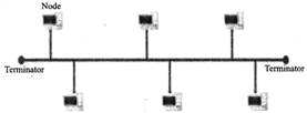
- Bus Topology: In contrast to point-to-point, in bus topology all device share single communication line or cable. All devices are connected to this shared line. Ethernet is commonly well protocol in networks connected in bus topology.
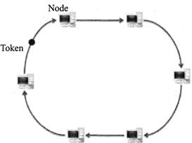
- Ring Topology: In ring topology, each host machine connects to exactly two other machines, creating a circular network structure. This topology use the token ring protocol for controlling access. Each workstation is connected to two other components on either side, and it communicates with these two adjacent neighbors. Data travels around the network, in one direction. Sending and receiving of data takes place by the help of TOKEN.
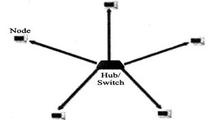
- Star Topology: In Star topology, all the components of network are connected to the central device called "hub" which may be a hub, a router or a switch. All the data on the star topology passes through the central device before reaching the intended destination. Hub acts as a junction to connect different nodes present in Star Network, and at the same time it manages and controls whole of the network. Depending on which central device is used, "hub" can act as repeater or signal booster.
- Mesh Topology: In this type of topology, a host is connected to one or two or more than two hosts. This topology may have hosts having point-to-point connection to every other hosts or may also have hosts which are having point to point connection to few hosts only.
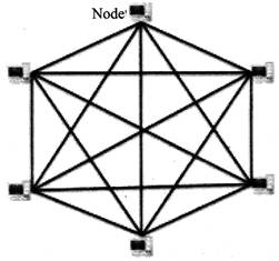
Hosts in Mesh topology also work as relay for other hosts which do not have direct point-to-point Iinks. Mesh technology comes into two flavors:
Full Mesh: All hosts have a point-to-point connection to every other host in the network. Thus for every new host n (n-1 )/2 cables (connection) are required. It provides the most reliable network structure among all network topologies.
Partially Mesh: Not all hosts have point-to-point connection to every other host. Hosts connect to each other in some arbitrarily fashion. This topology exists where we need to provide reliability to some host whereas others are not as such necessary.
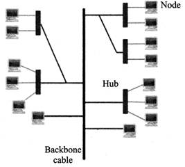
- Tree Topology: Also known as Hierarchical Topology is the most common form of network topology in use present day. This topology imitates as extended Star Topology and inherits properties of Bus topology this topology divides the network in to multiple levels/layers of network. Mainly in LANs, a network is bifurcated into three types of network devices. The lowest most is access-layer where user’s computer are attached. The middle layer is known as distribution layer, which works as mediator between upper layer and lower layer. The highest most layer is known as Core layer, and is central point of the network, i.e. root of the tree from which all nodes fork.
- Daisy Chain: This topology connects all its hosts in a linear fashion. Similar to Ring topology, all hosts in this topology are connected to two hosts only, except the end hosts. That is if the end hosts in Daisy Chain are connected then it represents Ring topology. Each link in Daisy chain topology represents single point of failure. Every link failure splits the network into two segment. Every intermediate host works as relay for its immediate hosts.
- Hybrid Topology: A network structure whose design contains more than one topology is said to be Hybrid Topology. Hybrid topology inherits merits and demerits of all the incorporating topologies. The above picture represents an arbitrarily Hybrid topology. The combining topologies may contain attributes of Star, Ring, Bus and Daisy-chain topologies. Most WANs are connected by means of dual Ring topology and networks connected to them are mostly Star topology networks. Internet is the best example of largest Hybrid topology.
NETWORK DEVICES
- Network Repeater: Network repeaters regenerate incoming electrical, wireless or optical signals. With physical media like Ethernet or Wi-Fi, data transmissions can only span a limited distance before the quality of the signal degrades. Repeaters attempt to preserve signal integrity and extend the distance over which data can safely travel. Actual network devices that serve as repeaters usually have some other name. Active hubs, for example, are repeaters. Active hubs are sometimes also called Multiport Repeaters but more commonly they are Just "hubs." Other types of passive hubs are not repeaters. In Wi-Fi, access points function as repeaters only when operating in so-called Repeater mode.
- Network Hub: A hub is a small Network Device. A hub joins multiple computers (or other network devices) together to form a single network segment. On this network segment, all computers can communicate directly with each other. Ethernet hubs are by far the most common type, but hubs for other types of networks such as USB also exist. A hub includes a series of ports that each accept a network cable, one port is reserved for "uplink” connections to another hub or similar device.
- Network Bridge: It reads the outermost section of data on the data packet, to tell where the message is going only the outermost hardware address of the packet. It reduces the traffic on other network segment since it does not send all packets. Bridges can be programmed to reject packets from particular network Bridging occurs at the data link layer of the OSI model. Bridge cannot read IP addresses. Bridge can read the ethernet data which gives the hardware address of the destination address. Bridges forward all broadcast messages.
- Network Router: It is a network device with interfaces in multiple networks whose task is to copy packets from one network to another. Router gives path to data packet to destination. Routers provide connectivity inside enterprises, between enterprises and the Internet, and within an Internet Service Provider (ISP). It operates at Layer 3 (Network Layer) of the OSI Model. Router works with static Routing manually configure by Network Administrator. Router works with Dynamic Routing which routers calculate automatically by different methods. Router stores calculate path in his Routing Table The network router will then use its routing table to make intelligent decisions about which packets to copy to which of its interfaces. The router will use this information to create a routing table. This process is known as routing.
- Network Switch: Network Switch is a small hardware device that joins multiple computers together within one local area network (LAN).
Network Switches operate at layer two (Data Link Layer) of the OSI model. Network switches appear nearly identical to network hubs, but a switch generally contains more intelligence (and a slightly higher price tag) than a hub. Unlike hubs. Switches are capable of inspecting data packets as they are received, determining the source and destination device of each packet, and forwarding them appropriately. By delivering messages only to the connected device intended. Switch conserves network bandwidth and offers generally better performance than a hub. Switch supports different bandwidth either 10/100mbps Fast Ethernet or Gigabit Ethernet (10/100/1000) standards.
- Gateway: A gateway is an interconnecting device which joins two different network together they are also known as protocol converters. It accepts packet formed for one protocol and converts the formatted packet into another protocol.
- CSU/DSU (Channel Service Unit/Data Service Unit): CSU/DSU is a hardware device about the size of an external modem that converts a digital data frame from the communications technology used on a local area network (LAN) into a frame appropriate to a wide-area network (WAN) and vice versa. The Channel Service Unit (CSU) receives and transmits signals from and to the WAN line and provides a barrier for electrical interference from either side of the unit. The CSU can also echo loopback signals from the phone company for testing purposes. The Data Service Unit (DSU) manages line control, and converts input and output between RS-232C, RS-449, or V.xx frames from the LAN and the time- division multiplexed (TDM) DSX frames on the T-l line. The DSU manages timing errors and signal regeneration. The DSU provides a modem-like interface between the computer as Data Terminal Equipment (DTE) and the CSU.
- Modem: Modem is a device that converts digital signal to analog signal (modulator) at the senders and converts back analog signal to digital signal (demodulator) at the receiver's end. A modem is always placed between a telephone line and a computer. A modem links home network to the Internet through Internet Service Provider (ISP). The high speed types of data outside your home aren't suitable for your direct use, so modems convert the data into digital Ethernet, which all the network equipment in your home can use.
The internet services that are outside your home (or business) which are supplied by your ISP are either DSL, cable, dial-up, or satellite. Modems are often combined with a router into a single unit, which then also gives you a firewall protecting of your network from attack. If your modem is not also a router, men you will probably want a router in addition to your modem.
- Ethernet Card: An Ethernet card is one kind of network adapter. These adapters support the Ethernet standard for high-speed network connections via cables. Ethernet cards are sometimes known as network interface cards (NICs).
DATA SIGNALS
When data is sent over physical medium it needs to be first converted into electromagnetic signals. Data itself can be analog such as human voice, or digital such as file on the disk. Data (both analog and digital) can be represented in digital or analog signals.
Digital Signals
Digital signals are discrete in nature and represents sequence of voltage pulses. Digital signals are used within the circuitry of a computer system.
Analog Signals
Analog signals are in continuous wave form in nature and represented by continuous electromagnetic waves.
BASIC COMMUNICATION MODES OF OPERATION
There are three basic modes of operation that can exist for any network connection, communications channel, or interface.
- Simplex Operation: In simplex operation, a network cable or communications channel can only send information in one direction; it's a "one-way street".
- Half-Duplex Operation: Technologies that employ half-duplex operation are capable of sending information in both directions between two nodes, but only one direction or the other can be utilized at a time. This is a fairly common mode of operation when there is only a single network medium (cable, radio frequency and so forth) between devices.
- Full-Duplex Operation: In full-duplex operation, a connection between two devices is capable of sending data in both directions simultaneously. Full-duplex channels can be constructed either as a pair of simplex links (as described above) or using one channel designed to permit bidirectional simultaneous transmissions. A full-duplex link can only connect two devices, so many such links are required if multiple devices are to be connected together.
COMMUNICAT30N MEDIUM
The Communication Medium plays an important role in Networks. If the medium works well and properly, then the speed of transferring data is good but if the medium is not working properly, then your data would w delayed or would not be sent or even can be lost during transmission. In Computer Networks, we call this seed of transmitting data, as date rate. The medium over which the information between two computer systems is sent, called Transmission Media.
Transmission media comes in two forms:
- Guided Media: All communication wires/cables comes into this type of media, such as UTP, Coaxial and Fiber Optics. In this media the sender and receiver are directly connected and the information is send (guided) through it.
- Unguided Media: Wireless or open air space is said to be unguided media, because there is no connectivity between the sender and receiver. Information is spread over the air, arid anyone including the actual recipient may collect the information.
CHANAL CAPACITY: The speed of transmission of information is said to be the channel capacity. We count it as data rate in digital word. It depends on numerous factors
BANDWIDTH: The physical limitation of underlining media.
ERROR-RATE: Incorrect reception of information because of noise.
ENCODING: Number of levels used for signaling.
MULTIPLEXING: Multiplexing is a technique to mix and send multiple data stream over a single media. This technique requires system hardware called Multiplexer for multiplexing steams and sending them on a media and De- Multiplexer which takes information from the media and distributes to different destinations.
SWITCHING: Switching is a mechanism by which data/information sent from source towards destination which are not directly connected. Networks have interconnecting devices, which receives data from directly connected sources, stores data, analyze it and then forwards to the next interconnecting device closest to the destination.
THROUGHPUT: Throughput is the amount of work that a computer can do in a given time period.
VARIOUS TYPES OF GUIDED OR WIRED TECHNOLOGIES
- Ethernet Cable or Twisted Pair Cable: A twisted pair cable is made of two plastic insulated copper wires twisted together to form a single media, which are surrounded by an insulating material and outs layer called jacket.
Out of these two wires only one carries actual signal and another is used for ground reference. The twists between wires is helpful in reducing noise (electromagnetic interference) and crosstalk. It is used as 2 short distance communication. E.g. Local Area networks used twisted pair cable.
There are two types of twisted pair cables available:
- Shielded Twisted Pair (STP) Cable -STP cables comes with twisted wire pair covered in metal foil this makes it more indifferent to noise and crosstalk.
- Unshielded Twisted Pair (UTP) Cable -UTP has seven categories, each suitable for specific use. In computer networks, Cat-5, Cat-5e and Cat-6 cables are mostly used. UTP cables are connected by RJ45 connectors.
- Coaxial Cable: Coaxial cables has two wires of copper. The core wire lies in center and is made of solid conductor. Core is enclosed in an insulating sheath. Over the sheath the second wire is wrapped around and that too in turn encased by insulator sheath. This all is covered by plastic cover. Because of its structure coax cables are capable of carrying high frequency signals than that of twisted pair cables. The wrapped structure provides it a good shield against noise and cross talk. Coaxial cables provide high bandwidth rates of up to 450 mbps. There are three categories of Coax cables namely, RG-59 (Cable TV), RG-58 (Thin Ethernet) and RG-11 (Thick Ethernet. RG stands for Radio Government. Cables are connected using BNC connector and BNC-T. BNC terminator is used to terminate the wire at the far ends.
- Power Lines: Power Line communication is Layer-1 (Physical Layer) technology which uses power cables to transmit data signals. Send in PLC modulates data and sent over the cables. The receiver on the other end de-modulates the data and interprets. Because power lines are widely deployed, PLC can make all powered devices controlled and monitored. PLC works in half-duplex. Two types of PLC exists:
Narrow band PLC - Narrow band PLC provides lower data rates up to 100s of kbps, as they work at lower frequencies (3000 kHz). But can be spread over several kilometers. Broad band PLC - Broadband PLC provides higher data rates up to 100s of Mbps and works at higher frequencies (1.8 - 250 MHz). But cannot be much extended as Narrowband PLC.
- Fiber Optics: Fiber Optic works on the properties of light. When light ray hits at critical angle it tends to refracts at 90 degree. This property has been used in fiber optic. The core of fiber optic cable is made of high quality glass or plastic. From one end of it light is emitted, it travels through it and at the other end light detector detects light stream and converts it to electric data form. Fiber Optic provides the highest mode of speed. It comes in two modes:
- Single mode fiber-Single mode fiber can carries single ray of light. .
- Multimode fiber- Multimode is capable of carrying multiple beams of light.
Fiber Optic also comes in unidirectional and bidirectional capabilities. To connect and access Fiber Optic special type of connectors are used.
Optical fibers allow transmission over longer distance at higher bandwidth which is not affected by electromagnetic field. The speed of optical fiber is hundred of times faster than coaxial cable. E.g. Wavelength Division Multiplexing and SONET network.
VARIOUS TYPES OF UNGUIDED OR WIRELESS TECHNOLOGIES
- Wireless Transmission: Wireless transmission is a form of unguided media. Wireless communication involves no physical link established between two or more devices, communicating wirelessly. Wireless signals are spread over in the air and are received and interpret by appropriate antennas. When an antenna is attached to electrical circuit of a computer or wireless device, it converts the digital data into wireless signals and spread all over within its frequency range. The receptor on the other end receives these signals and converts them back to digital data. A little part of electromagnetic spectrum can be used for wireless transmission.
- Radio Transmission: Radio frequency is easier to generate and because of its large wavelength it can penetrate through walls and alike structures. Radio waves can have wavelength from 1 mm - 100,000 km and have frequency ranging from 3 Hz (Extremely Low Frequency) to 300 GHz (Extremely High Frequency). Radio frequencies are sub-divided into six bands. Radio waves at lower frequencies can travel through walls whereas higher RF travel in straight line and bounces back. The power of low frequency waves decreases sharply as it covers longer distance. High frequency radio waves have more power.
Lower frequencies like (VLF, LF, MF bands) can travel on the ground up to 1000 kilometers, over the earth's surface.
- Microwave Transmission: Electromagnetic waves above 100 MHz tend to travel in a straight line and signals over them can be sent by beaming those waves towards one particular station. Because Microwaves travels in straight lines, both sender and receiver must be aligned to be strictly in line-of-sight. Microwaves can have wavelength ranging from 1 mm - 1 meter and frequency ranging from 300 MHz to 300 GHz. Microwave antennas concentrate the waves making a beam of it. Microwaves are higher frequencies and do not penetrate wall like obstacles. Microwaves transmission depends highly upon the weather conditions and the frequency it is using.
- Infrared Transmission: Infrared waves lies in between visible light spectrum and microwaves. It has wavelength of 700 nm to 1 mm and frequency ranges from 300 GHz to 430 THz. Infrared waves are used for very short range communication purposes such as television and it's remote. Infrared travels in a straight line so they are directional by nature. Because of high frequency range, Infrared do not cross wall like obstacles.
- Light Transmission: Highest most electromagnetic spectrum which can be used for data transmission is light or optical signaling. This is achieved by means of LASER. Because of frequency light uses, it tends to travel strictly in straight line. So the sender and receiver must be in the line-of-sight. Because laser transmission is unidirectional, at both ends of communication laser and photo-detectors needs to be installed. Laser beam is generally 1mm wide so it is a work of precision to align two far receptors each pointing to lasers source.
CLIENT-SERVER MODEL
In client-server model, any process can act as Server or Client. This not the machine or size of the machine or its computing power which makes it server but it is the feature of serving request that makes it server.
Client-server architecture (client/server) is a network architecture in which each computer or process .on the network is either a client or a server. Servers are powerful computers or processes dedicated to managing diss. drives (file servers), printers (print servers), or network traffic (network servers). Clients are PCs or workstations on which users run applications. Clients rely on servers for resources, such as files, devices, and. even processing power.
PEER TO PEER MODEL
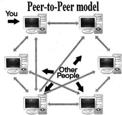
Another type of network architecture is known as a peer-to-peer architecture because each node has equivalent responsibilities. This computer network selies on computing power at the edges of a connection rather than in the network itself.
Peer to Peer computing or Networking is a distributed application architecture that partitions tasks or workloads between Peers, Peers are equaly privileged and equivalent participants in the Application Architecture so this Network is known as peer to peer architecture.