Basic Electricity
Category : Railways
Basic Electricity
Electricity
Electricity exists in the smallest particle in nature called the atom. The atom is the basic building block of matter. An atom is so small that human eyes cannot see it. We only see them with the help of very powerful magnifying devices.
Illustration of an atom given below:
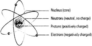
In the atom, there are three sub-atomic particles — Protons, Neutrons and Electrons. Protons and Neutrons are located right in the nucleus (centre or core) of the atom. Around the nucleus, here are electrons that are constantly moving very quickly. The electrons move because they have some energy. Neutrons have no charges. Protons are positively charged. Electrons are negatively charged, and they encircle the nucleus. Elections encircle the nucleus because opposite charges (negative charge electrons and positive charge protons) are attracted to each other, and alike charges tend to move away from each other.
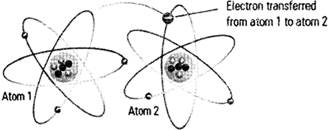
The encircling electron can move from one atom to the other.
When Protons and fast moving Electrons interact, electricity is produced. to simple terms, electricity is the interaction of Protons in the atom and the fast moving of Electrons around it. It is the flow of' electrons
BASIC ELECTRICITY
Electricity is the flow of electrons from one place to another. Electrons can flow through any material, but does so more easily in some than in others.
Since electrons are very small, as a practical matter they are usually measured in very large number. A Coulomb is
\[6.24\times {{10}^{18}}\]
electrons. However, electricians are mostly intersted in electrons in motion. The flow of electons is called current, and is measueed in AMPS. One amp is equal to a flow of one coulomb per second through a wire.
Making electrons flow through a resistance reqires an attractive force to pull them. This force, called Electro-Motive Force or EMF, is measured in volts. A Volt is the force required to push Amp through I Ohm of resistance.
As electrons flow through a risstance, it performs a certain amount of work. It may be in the form of heat or a magnetic field or motion, but it does something. That work is called Power, and is measured in Watts. One Watt is equal to the work performed by 1 Amp pushed by 1 Volt through a resistance.
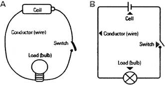
Electrical Circuit
An electrical circuit is a path or line through which an electrical current flows. The path may be closed (joined at both ends), making it a loop. A closed circuit makes electrical current flow possible. It may also be an open circuit where the electron flow is cut short because the path is broken. An open circuit does not allow electrical current to flow. Below is a basic set of symbols that you may find on circuit diagrams.
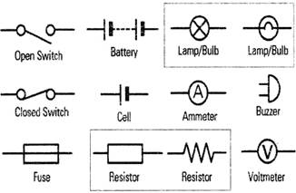
It is very important to know the basic parts of a simple circuit and the symbols that relate to them. A simple circuit has conductors, a switch, a load and a power source. The functions of each part given below:
Conductors
These are usually copper wires with no insulation. They make the path through which the electricity flows. One piece of the wire connects the current from the power source (cell) to the load. The other piece connects the load back to the power source.
Switch
The switch is simply a small gap in the conductor where you can close or open the circuit. When the switch is closed, the circuit is closed and electricity flows.
The Load
The load is a small light bulb or buzzer that lights when the circuit is turned on. The load is also known as a resistor.
Cell
The power source is a cell. (Note that more than one cell put together is known as a battery)
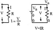
Ohms Law
At a constant temperature, the electrical current flowing through a fixed linear resistance is directly proportional to the voltage applied across it, and also invesely proportional to the resistance. This relationship between the Voltage, Current and Resistance forms the basis of Ohms Law and is shown below.
Ohms Law Relationship
\[\text{Current,}\,\,\text{(I)}=\frac{\text{Voltage,}\,\,\text{(}V)}{\text{Resistance,}\,\,(R)}in\,\,Amperes,\,\,(A)\]
By knowing any two values of the Voltage, Current or Resistance quantities we can use Ohms Law to find the third unknown value.
Electronic Circuit
Electronic circuits are integral parts of nearly all of the technological advancement in our life. Television, radio, phones and computers immediately come to mind, but electronics are also used in automobiles, kitchen appliances, medical equipment and industrial controls.
At the heart of these electrical devices are made by assembly of electrical components. These component are classified in two categories i.e., active components and passive components. Active components are: semiconductors, transistors, diodes and triodes, current source, voltage source. However, these devices could not function without much simpler components known as passive component these include resistors, capacitors and inductors.
Concepts of Resistance
Resistance is the opposition that a substance offers to the flow of electric current. It is represented by the letter R. The standard unit of resistance is the ohm & written as the uppercase Greek letter omega:
\[\Omega\]
In general, when the applied voltage is held constant, the current in a direct-current (DC) electrical circuit is inversely proportional to the resistance.
\[i\propto 1/r\]
The electrical resistance per unit length, area, or volume of a substance is known as resistivity. Resistivity is often specified for copper and aluminum wire, in ohms per kilometer. Resistance contrasts with conductance, which is a measure of the ease with which electrical current flows through a substance.
The general symbol of resistance:
![]()
Grouping of Resistors
Two types of groupings of resistors are in common use. These are:
Equivalent resistance of the combination is defined as a single resistance which allows the same current to flow as the given combination when the same potential difference is applied across it.
Series Combination
You can connect many resistors in series by joining them end-to-end such that the same current passes through all the resistors.
\[V={{V}_{1}}+{{V}_{2}}\]
\[V=I{{R}_{1}}+I{{R}_{2}}\]
\[V=I\,\,({{R}_{1}}+{{R}_{2}})\]
\[V=IRs\]
\[Rs={{R}_{1}}+{{R}_{2}}\]
The equivalent resistance of a series combination of resistors is equal to the sum of individual resistances.
Parallel Combination
You can connect the resistors in parallel by joining their one end at one point and the other ends at another point. In parallel combination, same potential difference exists across all resistors.
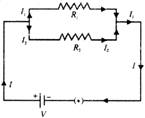
The main current divides into two parts.
\[{{I}_{1}}=V/{{R}_{1}}\]
\[{{I}_{2}}=V/{{R}_{2}}\]
\[I={{I}_{1}}+{{I}_{2}}\]
\[I=V\,\,(1/{{R}_{1}}+1/{{R}_{2}})\]
\[I=V/{{R}_{P}}\]
\[1/{{R}_{P}}=1/{{R}_{1}}+1/{{R}_{2}}\]
Concept of Capacitor
Capacitor is a passive element that stores electric charge statistically and temporarily as an static electric field. Almost all things can store some electrical energy and therefore have capacitance.
Conductance is the measure of how well an element will conduct electric current.
Mathematically, it is reciprocal of resistance.
G=1/R
Where,
G= Conductance
R= Resistance
Unit of conductance is mho
\[(\mho )\]
or siemen.
A typical capacitor consists of two conducting surfaces (usually metal plates) separated by an insulating material like air, rubber, or paper, this insulating material is called a dielectric.
The capacitance formula of the capacitor is represented by,
\[C=\frac{\in \,\,A}{d}\]
The general Symbol of capacitance:
![]()
Grouping of Capacitors
Capacitors are very important elements of electrical and electronic circuit Sometimes a capacitance of a proper value may not be available in such situations, grouping of capacitors helps to obtain desired (smaller or larger) value of capacitance with available capacitors Two most common capacitor groupings are:
Parallel Grouping of Capacitors
In parallel grouping, one plate of each capacitor is connected to one terminal and the other plate is connected to another terminal battery. In parallel combination, potential difference across each capacitor is the same.
The equivalent capacitance of a number of capacitors joined in parallel is equal to the sum of the individual capacitances.
Series Grouping of Capacitors
In the series combination of capacitors, the first plate of the first capacitor is connected to the electrical source. The second plate of the first capacitor is connected to the first plate of the second plate of second capacitor is connected to first plate of the next capacitor of the combination and so on. The second plate of last capacitor of the combination is connected to the electrical source.
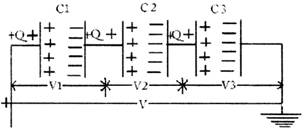
Each capacitor receives the same charge of magnitude q.
\[{{V}_{1}}=q/{{C}_{1}}\]
\[{{V}_{2}}=q/{{C}_{2}}\]
\[{{V}_{3}}=q/{{C}_{3}}\]
\[V={{V}_{1}}+{{V}_{2}}+{{V}_{3}}\]
\[q/Cs=q\,\,(1/{{C}_{1}}+1/{{C}_{2}}+1/{{C}_{3}})\]
\[1/Cs=1/{{C}_{1}}+1/{{C}_{2}}+1/{{C}_{3}}\]
The reciprocal of equivalent capacitance of any number of capacitors connected in series is equal to the sum of the reciprocals of individual capacitances.
Inductance
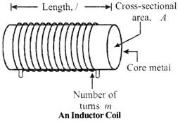
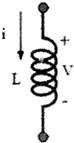
An inductor is an electronic component consisting simply of a coil of wire. A constant electric current running through an inductor produces a magnetic field. If the current changes, so does the magnetic field. The unit for inductance is the Henry (H). In other words, an inductor can be defined as an energy storage device which stores energy in form of magnetic field. Any conductor of electric current has inductive properties and may be regarded as an inductor. But in order to enhance the inductive effect, a practical inductor is usually formed into a cylindrical coil with many turns of conducting wire as shown in the figure.
Inductors
An inductor is a passive element designed to store energy in its magnetic field. Inductors find numerous applications in electronic and power systems. They are used in power supplies, transformers, radios, TVs, radars, electric motors, etc.
The general Symbol of inductor
Grouping of inductors
Series inductors
When inductors are connected in series, the total inductance is the sum of the individual inductors' inductances. To understand why this is so, consider the following: the definitive measure of inductance is the amount of voltage dropped across an inductor for a given rate of current change through it. If inductors are connected together in series (thus sharing the same current, and seeing the same rate of change in current), then the total voltage dropped as the result of a change in current will be additive with each inductor, creating a greater total voltage than either of the individual inductors alone. Greater voltage for the same rate of change in current means greater inductance.
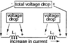
Thus, the total inductance for series inductors is more than any one of the individual inductors' inductances. The formula for calculating the series total inductance is the same form as for calculating series resistances:
Series Inductances
\[{{L}_{total}}={{L}_{1}}+{{L}_{2}}+....{{L}_{n}}\]
Parallel inductors
When inductors are connected in parallel, the total inductance is less than any one of the parallel inductors' inductances. Again, remember that the definitive measure of inductance is the amount of voltage dropped across an inductor for a given rate of current change through it. Since the current through each parallel inductor will be a fraction of the total current, and the voltage across each parallel inductor will be equal, a change in total current will result in less voltage dropped across the parallel array than for any one of the inductors considered separately. In other words, there will be less voltage dropped across parallel inductors for a given rate of change in current than for any of those inductors considered separately, because total current divides among parallel branches. Less voltage for the same rate of change in current means less inductance.
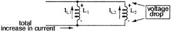
Thus, the total inductance is less than any one of the individual inductors' inductances. The formula for calculating the parallel total inductance is the same form as for calculating parallel resistances:
Parallel inductances
\[{{L}_{total}}=\frac{1}{\frac{1}{{{L}_{1}}}+\frac{1}{{{L}_{2}}}+.....\frac{1}{{{L}_{n}}}}\]
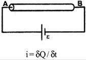
Electric Current
It is defined as the rate of flow of charge through a particular area of cross section of a conductor.
The direction of flow of current is always from a region of higher potential to a region of lower potential.
The direction of current is opposite to direction of flow of electrons because they carry negative charge and will move from a region of higher potential. Flow of electric charge constitutes electric current.
We define it mathematically as For a given conductor, if' ‘dQ' charge flows through a cross-section of area A in time 'dt', then the electric current through the conductor is given as i = dQ / dt
Where
i is a current (scalar quantity).
\[\delta Q\]
is the charge flows through a cross-section of area A.
\[\delta \tau\]
is a time.
Electric Voltage
Voltage is often referred to as "electric potential", which then must be distinguished from electric potential energy by noting that the "potential" is a "per-unit-charge" quantity. In other word. Voltage is a quantitative expression of the potential difference in charge between two points in an electrical field. The greater the voltage, the greater the flow of electrical current through a conducting or semiconducting medium for a given resistance to the flow.
Voltage is symbolized by an uppercase non- italic letter V or E. The standard unit of Voltage is electric potential energy per unit charge, measured in joules per coulomb (= volts). One volt will drive one coulomb
\[(6.24\times {{10}^{18}})\]
charge carriers, such as electrons, through a resistance of one ohm in one second.
Where
V= Voltage
I= Current
R= Resistance
RMS Voltage Equation
\[{{V}_{RMS}}={{V}_{m}}\frac{1}{\sqrt{2}}={{V}_{m}}\times 0.7071\]
then the RMS voltage
\[({{V}_{RMS}})\]
of a sinusoidal waveform is determined by multiplying the peak voltage value by 0.7071, which is the same as one divided by the square root of two
\[(1/\sqrt{2})\]
The RMS voltage, which can also be referred to as the effective value, spends on the magnitude of the waveform and is not a function of either the waveforms frequency nor its phase angle.
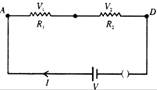
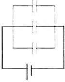
Basic circuit
A simple circuit has a cell providing current (switch on) along a path (wire), to a load (resistor) and back to the other end of the cell as shown in below diagram.
As the voltage gets to the resistor (load), there is a power drop, because the resistor uses some of the electricity up to produce heat and light. This means that the voltage that ends up at the other side of the cell is reduced.
Short Circuit
In a short circuit, there is no load. For many reasons, the wires in a circuit can find a short-cut, bypassing the load (and other components). This causes the same voltage from the cell to flow to the other end of the cell. When this happens the high voltage causes the wires to heat up and catch fire.
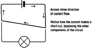
Why there could be a short circuit:
A short circuit can cause heating, melting of wires, harmful smoke and smell, and blinding light during welding.
Circuit protection
It is very important that electrical devices in homes, cars, aeroplanes and other complex machines are protected from higher voltage than the wires are designed to take—otherwise, the devices can break and even catch fire.
In real life electrical circuits, it is possible that wires (conductors) loose their insulation and come into contact with the ground or other conductors. If that happens, the voltage in the wire will have no resistor (load) and the same high voltage will be returned to the source of power.
This can result in overheating, as there is way too much voltage than the wires can take. Overheating will then cause melting and eventually a break (open) in the circuit.
One way to protect a circuit is to add a fuse, circuit breaker or thermal breaker to the circuit.
Fuse
A fuse is simply a strip of alloy wire (made of bismuth and tin), which is connected to the circuit. The fuse is usually designed to take specific volumes of electricity (voltage). For example is a 3 amp fuse is fixed into a circuit—it cannot take any more than 3 amps of electricity. If for any reason, there is a surge or increase in the voltage, the fuse will melt immediately and break. This will stop the flow of high voltage and prevent any potential damage to the circuit or device.


You need to login to perform this action.
You will be redirected in
3 sec

