Phase
Category : JEE Main & Advanced
Physical quantity which represents both the instantaneous value and direction of alternating quantity at any instant is called it's phase. It's a dimensionless quantity and it's unit is radian.
If an alternating quantity is expressed as \[X={{X}_{0}}\sin (\omega \,t\pm {{\varphi }_{0}})\] then the argument of \[\sin (\omega \,t+\varphi )\] is called it's phase. Where \[\omega t=\]instantaneous phase (changes with time) and \[{{\phi }_{0}}=\]initial phase (constant w.r.t. time)
Some important values
| Nature of wave form | Wave form | r.m.s. value | average value |
Form factor \[{{R}_{f}}=\frac{r.m.s.\,value}{Average value}\] |
Peak factor \[{{R}_{p}}=\frac{Peak value }{r.m.s.\,value}\] |
| Sinusoidal | 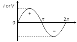 |
\[\frac{{{i}_{0}}}{\sqrt{2}}\] | \[\frac{2}{\pi }{{i}_{0}}\] | \[\frac{\pi }{2\sqrt{2}}=1.11\] | \[\sqrt{2}=1.41\] |
| Half wave rectified | 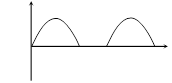 |
\[\frac{{{i}_{0}}}{2}\] | \[\frac{{{i}_{0}}}{\pi }\] | \[\frac{\pi }{2}=1.57\] | 2 |
| Full wave rectified | 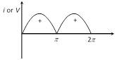 |
\[\frac{{{i}_{0}}}{\sqrt{2}}\] | \[\frac{2{{i}_{0}}}{\pi }\] | \[\frac{\pi }{2\sqrt{2}}\] | \[\sqrt{2}\] |
| Square or Rectangular | 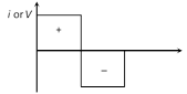 |
\[{{i}_{0}}\] | \[{{i}_{0}}\] | 1 | 1 |
(1) Phase difference (Phase constant) : The difference between the phases of currents and voltage is called phase difference. If alternating voltage and current are given by \[V={{V}_{0}}\sin (\omega \,t+{{\varphi }_{1}})\] and \[i={{i}_{0}}\sin (\omega \,t+{{\varphi }_{2}})\] then phase difference \[\phi ={{\phi }_{1}}-{{\phi }_{2}}\] (relative to current) or \[\varphi ={{\varphi }_{2}}-{{\varphi }_{1}}\] (relative to voltage)
(2) Time difference : If phase difference between alternating current and voltage is \[\phi \] then time difference between them is given as \[\text{T}\text{.D}\text{.}=\frac{T}{2\pi }\times \varphi \]
(3) Phasor diagram : A diagram representing alternating current and alternating voltage (of same frequency) as vectors (phasors) with the phase angle between them is called a phasor diagram.
While drawing phasor diagram for a pure element (e.g. R, L or C) either of the current or voltage can be plotted along X-axis. But when phasor diagram for a combination of elements is drawn then quantity which remains constant for the combination must be plotted along X-axis so we observe that
(i) In series circuits current has to be plotted along X-axis.
(ii) In parallel circuits voltage has to be plotted along X-axis.


You need to login to perform this action.
You will be redirected in
3 sec

