Introduction to Logic Gates and Number System
Category : 9th Class
Introduction to Logic Gates and Number System
Introduction
A logic gate is an idealized or physical device implementing a Boolean function, that take inputs and produces a single logic output.
Computer are made up of logic gates. Logic gates take information coming in and output different information depending on what type of gate they are.
In 1938, Claude E. Shannon introduced a two ? valued Boolean algebra called Switching Algebra, which applied the concept of Boolean Algebra to the design of electrical circuits.
Truth Table and Logic Gates
Truth Table
A truth table is a representation of all possible combinations of Input values and their result in a tabular format. If the result of a logical expression of logical statement is always true or 1, it is known as Tautology. If the result expression or logical statement is always false or 0, it is known as Fallacy.
|
A |
B |
C |
Decimal Equivalent |
|
0 |
0 |
0 |
0 |
|
0 |
0 |
1 |
1 |
|
0 |
1 |
0 |
2 |
|
0 |
1 |
1 |
3 |
|
1 |
0 |
0 |
4 |
|
1 |
0 |
1 |
5 |
|
1 |
1 |
0 |
6 |
|
1 |
0 |
1 |
7 |
The number of rows in a truth table is calculated as 2n where n is the total number of variables. Therefore if there are three variables A, B and C, then the possible values will be 23 = 8 combinations. It can be represented a follows:
Thus, for n variable, the number of possible combinations of inputs will be 2n, which are binary representations of the Integer from 0 to (2n-1).
The logical operators are:
i) NOT or Negation: The operator is unary operator because it operates on single variable. This operator is also called complement and the symbol for this is '~' or '-' or '' '. Thus, if the letter x stands for a logical statement then the statement ~ a or a' means complement of x. The table clearly shows that if x is True, x' is False, x' is True.
|
X |
X' |
|
0 |
1 |
|
1 |
0 |
ii) AND (Conjunction) Operator: This operator operates on two or more operands on two or more operands. AND operator is used to perform logical multiplication and the symbol for AND operator is dot (' . ').
|
X |
X' |
F |
|
0 |
0 |
0 |
|
0 |
1 |
0 |
|
1 |
0 |
0 |
|
1 |
1 |
1 |
iii) OR (Disjunction) Operator: OR operator is used to perform logical Addition and the symbol for OR operator is '+' plus.
|
X |
X' |
F |
|
0 |
0 |
0 |
|
0 |
1 |
0 |
|
1 |
0 |
0 |
|
1 |
1 |
1 |
Logic Gates
A gate is a circuit which takes one or more inputs and generate only one output. A gate is a digital circuit because it can take only two values, i.e. either high or low. Logic gates use the binary operators AND, OR and NOT There are three fundamental logic gates which are as follows:
1. AND Gate
2. OR Gate
3. NOT Gate
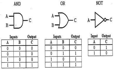
AND Gate, Logic diagram, truth table
AND Gate works on two or more inputs which result in a single output. When all the inputs are 1 or high, then the output is 1 otherwise the output is 0. The truth table and logic gate for AND is given as:
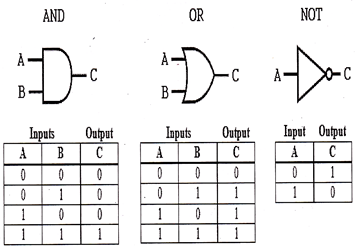
OR Gate, Logic Diagram, Truth Table
OR Gate works on two or more inputs which result in a single output. When any of the input signal is 1, the output signal is 1 and if all input signal is 0, the output signal will be 0. The truth table and logic gate for OR is given as;
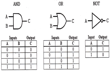
NOT Gate, Logic Diagram, Truth Table
NOT gate works on a single input signal and generates a single output signal. The output state is a negation or complement of an input signal which is denoted by (') or (-5 sign. The truth table and logic gate for NOT is given as:
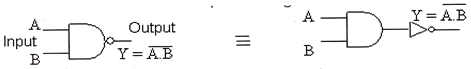
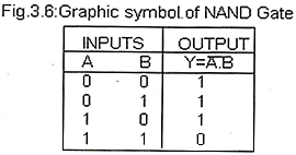
NAND Gate, Logic Diagram Truth Table
This gate is the combination of AND or NOT gate. The NAND gate has two or more input but only on output. It produces output 1 when any of the input is 0.
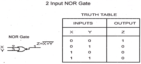
NOR Gate, Logic Diagram, Truth Table
The NOR gate is the combination of NOT and OR gate. The NOR gate has two or more input but only on output. It produces output 1 when all inputs are 0.
Number System
The number of digits in the system determines the base of any number system, such as decimal and binary. Basically binary is a base - 2 number system as it uses two basic digits. Thus it means that the whole Binary number system depends on the two basic digits. Whereas Decimal is a base-10 system since it uses ten digits and these are 0, 1, 2, 3, 4, 5, 6, 7, 8 and 9.
Decimal Number System
A system with base - 10 is a decimal number system. Thus it means that there are ten basic digits on which the decimal number system depends. The digits are 0, 1, 2, 3, 4, 5, 6, 7, 8 and 9. By using these ten digits all the numbers in decimal number system are written. Thus the place value of a digit in a number increases the power from right to left.
The following are the place value of each digit of number 5471:
v The place value of 1 is: 1*10° = 1
v The place value of 6 is: ![]()
v The place value of 3 is: ![]()
v The place value of 5 is: ![]()
Binary Number System
A number system with a base-2 is known as binary number system. The whole binary number system depends on two digits these are 0 and 1, respectively. By using these two digits the number in binary number system are written. Thus the place value of a digit in a number increases in the power of 2 from right to left.
The following example shows how to convert binary number 1010101 into decimal number:
|
Power of |
2 |
6 |
5 |
4 |
3 |
2 |
1 |
0 |
|
Binary number |
1 |
0 |
1 |
0 |
1 |
0 |
1 |
|
v The place value of 1 is: ![]()
v The place value of 0 is: ![]()
v The place value of 1 is: ![]()
v The place value of 0 is: ![]()
v The place value of 1 is: ![]()
v The place value of 0 is: ![]()
v The place value of 1 is: ![]()
v The decimal number ![]()
Decimal to Binary Conversion
While converting decimal to binary there are two methods. These are:
v Comparing with descending powers of two and subtraction
v Short division by two with remainder
Comparing with descending powers of two and subtraction:
Hexadecimal Number System
The hexadecimal number system is based on 16. Therefore, it means, there are 16 basics digits on which whole hexadecimal number system depends. The digits are 0, 1, 2, 3, 4, 5, 6, 7, 8, 9, 10, 11, 12, 13, 14 and 15, where as the numbers 10, 11, 12, 13, 14, and 15 are also represented as A, B, C, D, E and F. By using these 16 digits all the numbers in Hexadecimal number system are written. Thus the place value in hexadecimal system is increased in the power of 16 from right to left.
One's Complement
One's component is a system that is used to represent negative numbers. To take 1's complement of binary digit, replace all 1's with 0's and all 0's with 1's.
Example
1's complement of 110001 is 001110.


You need to login to perform this action.
You will be redirected in
3 sec

